Efficient Half Size Dipole for 40 meters

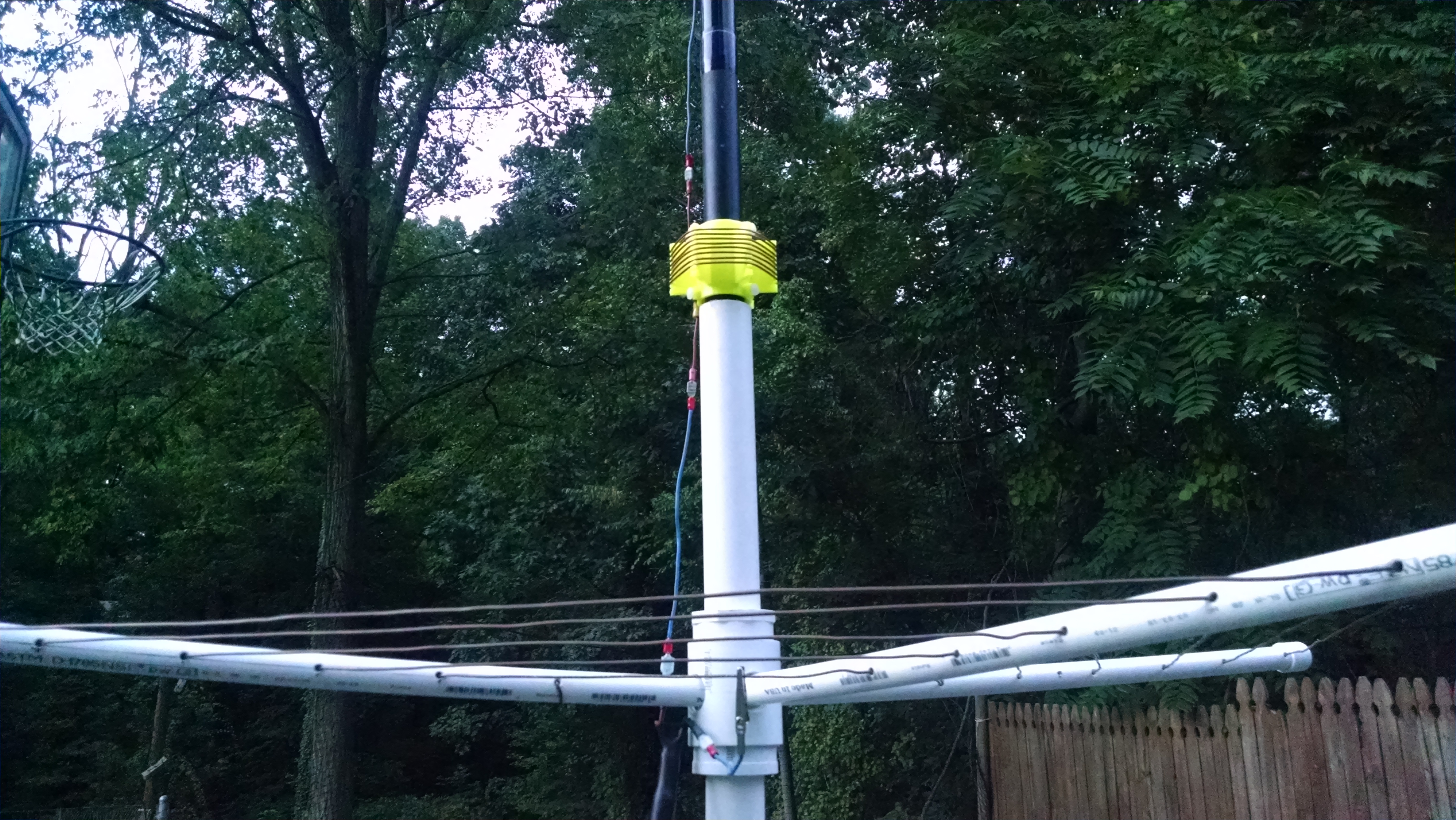
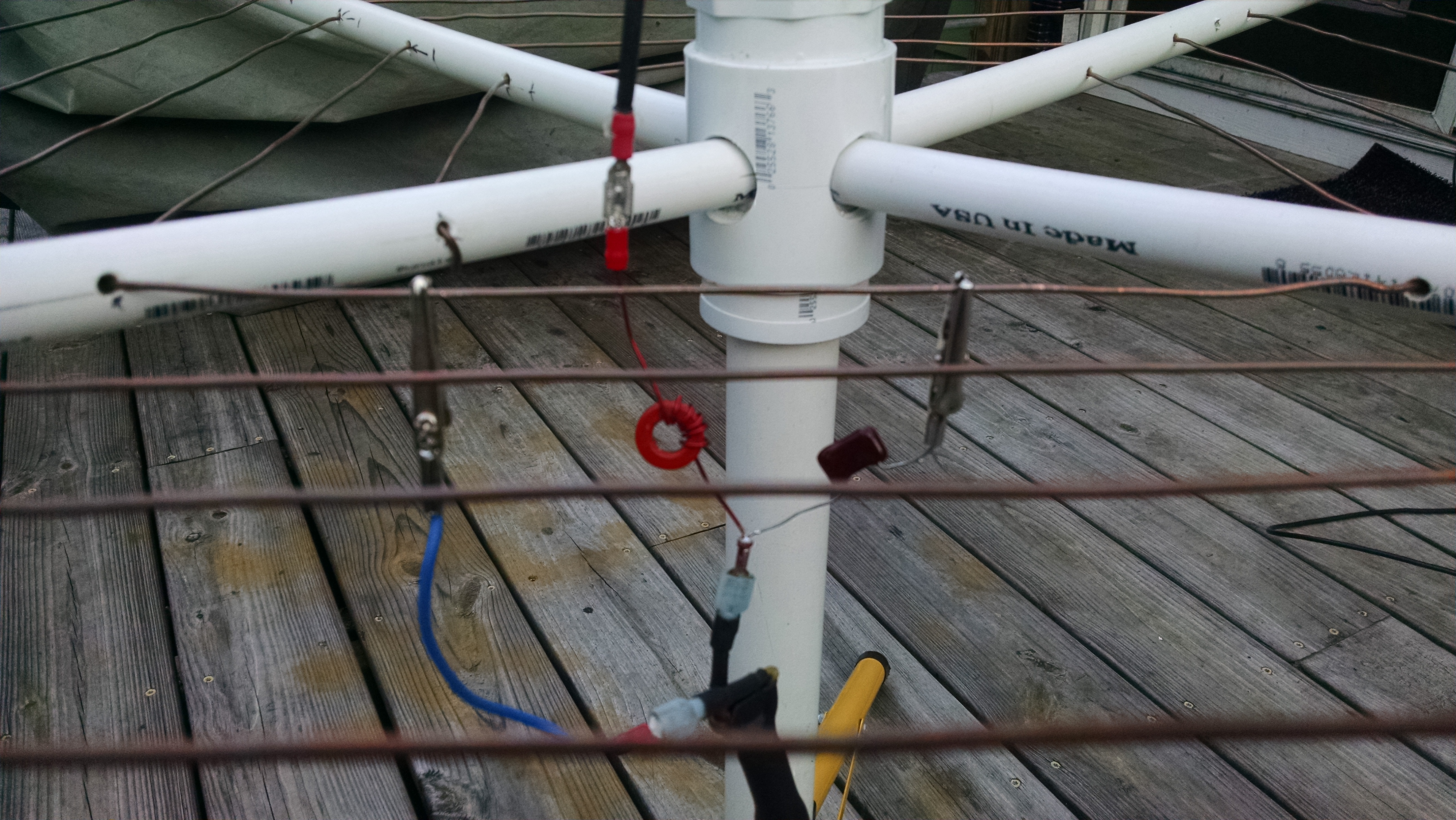
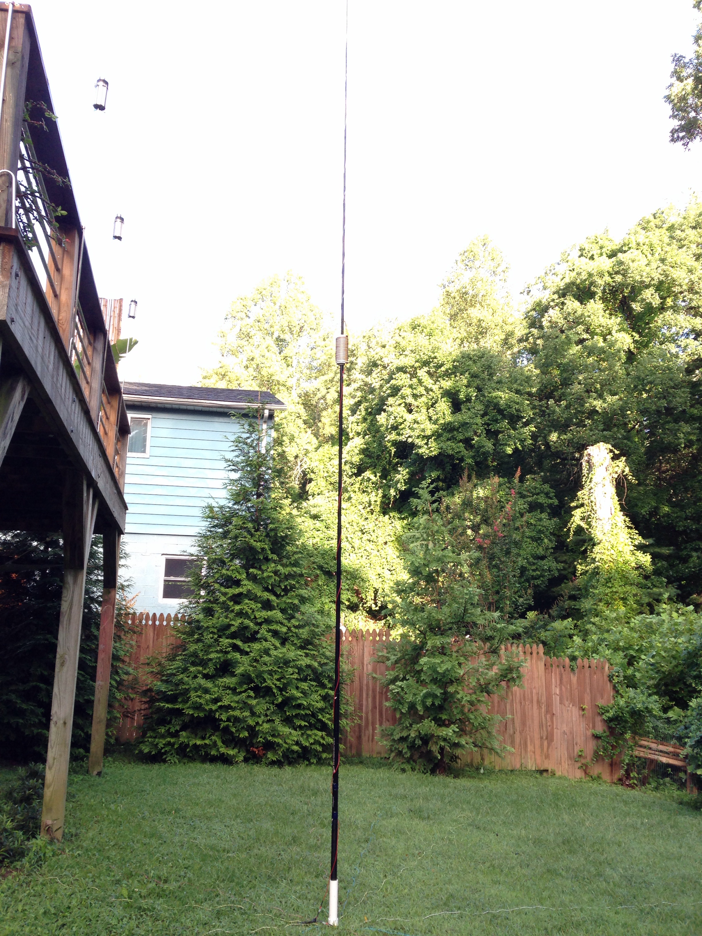
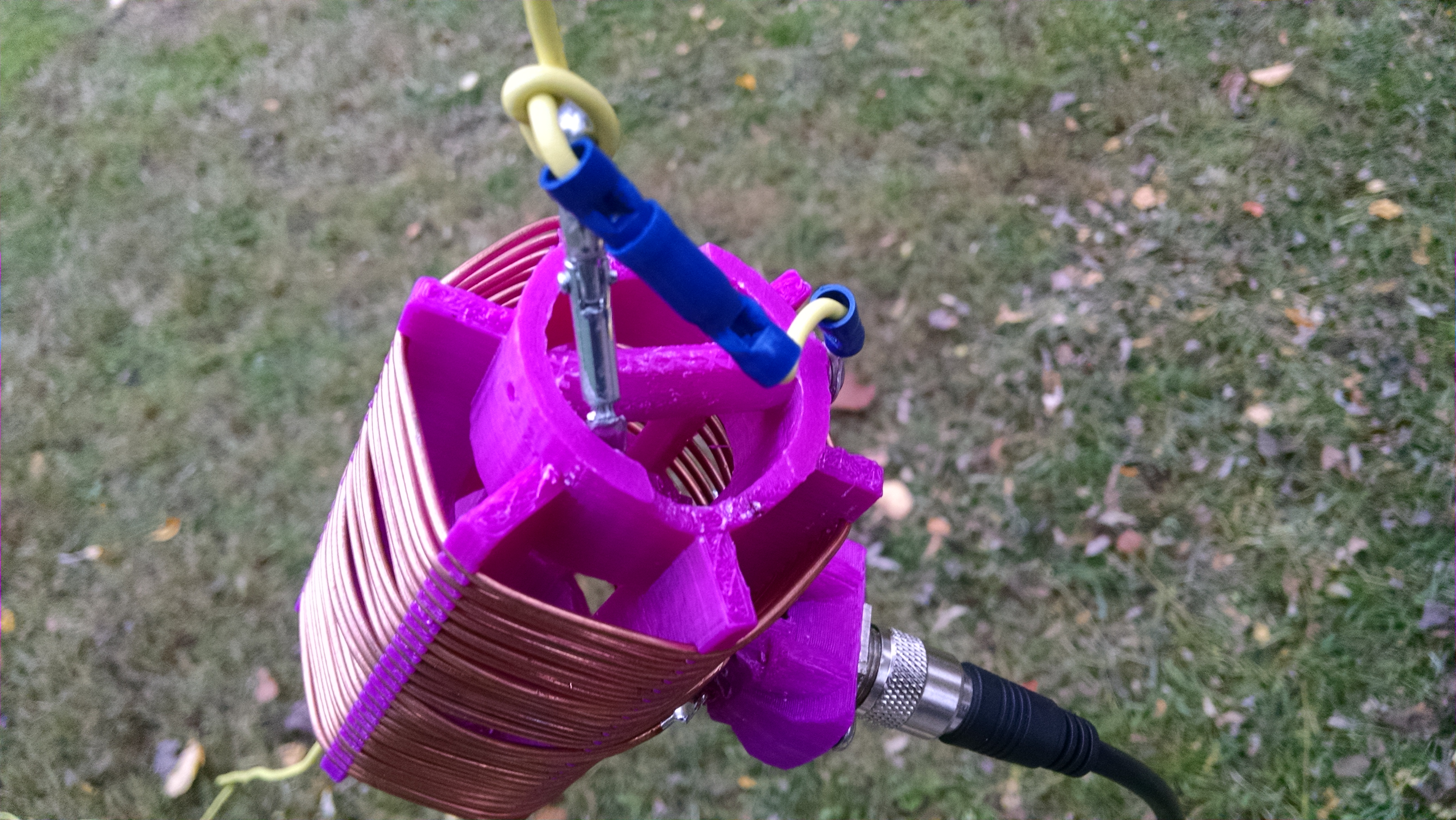
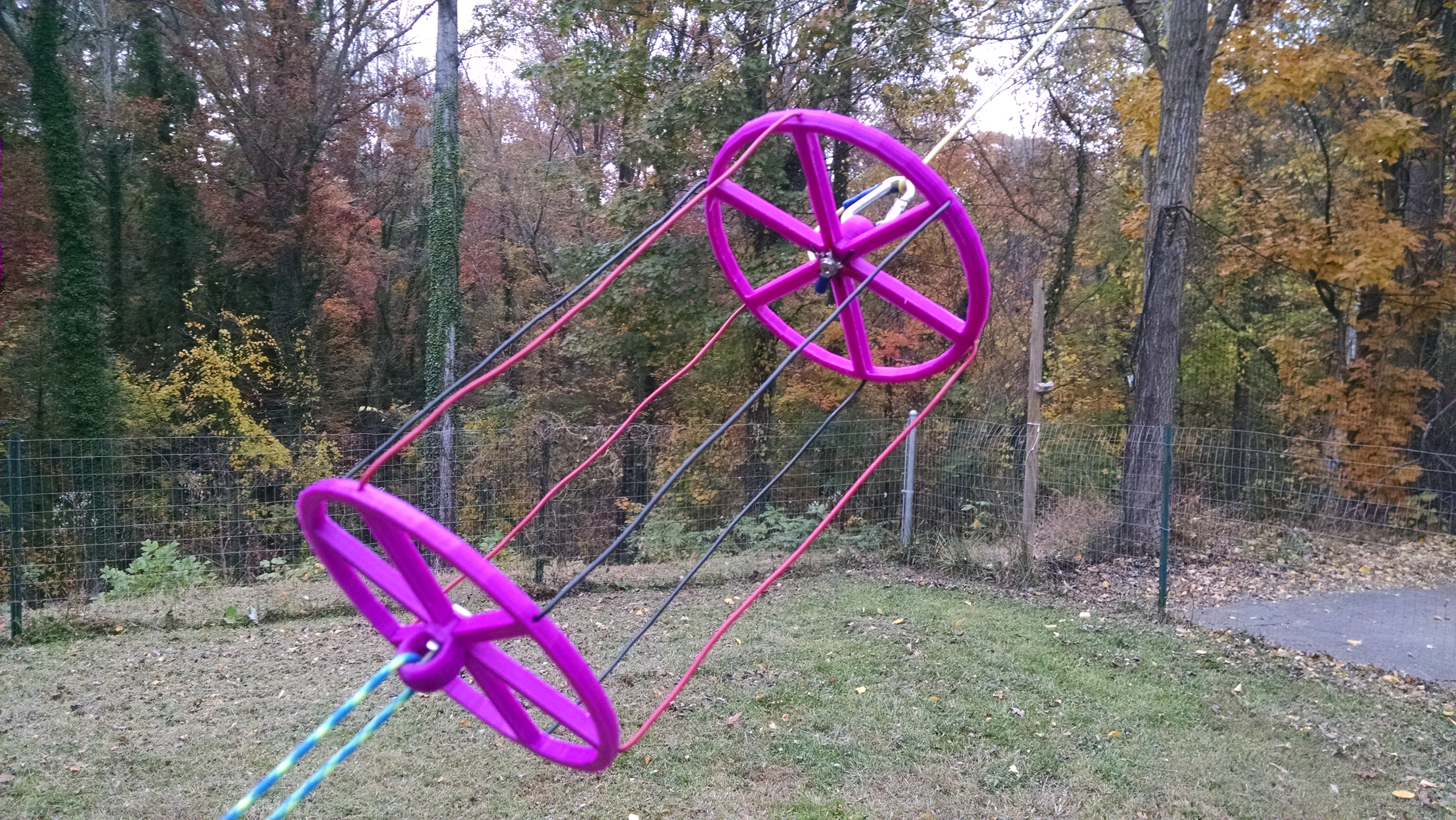
In my continuing saga of antenna experiments, I have designed  a 30 (a little less than 1/2 normal size) foot long 40 meter dipole that is a solid performer. The goal was to make it short enough that it would work well in portable applications as a vertical or sloper hung from a tree.  It is center fed with one continuous loading coil tapped at the center two turns to a SO-239 type jack for coax. A balun is not necessary because of  the tapped connection to the loading coil. Along with the loading coil, there are two cylindrical capacitive hats which  replace about six  feet of wire each. The hats improve current distribution, bandwidth and efficiency,  allowing for a smaller loading coil. The hats are lightweight and flatten out for very easy transport. The antenna uses carabiners and inline connectors to allow quick connect and disconnect for setup and removal.

Link To STL Files

https://www.adrive.com/public/F8Fsz4/Antenna%20Forms.zip

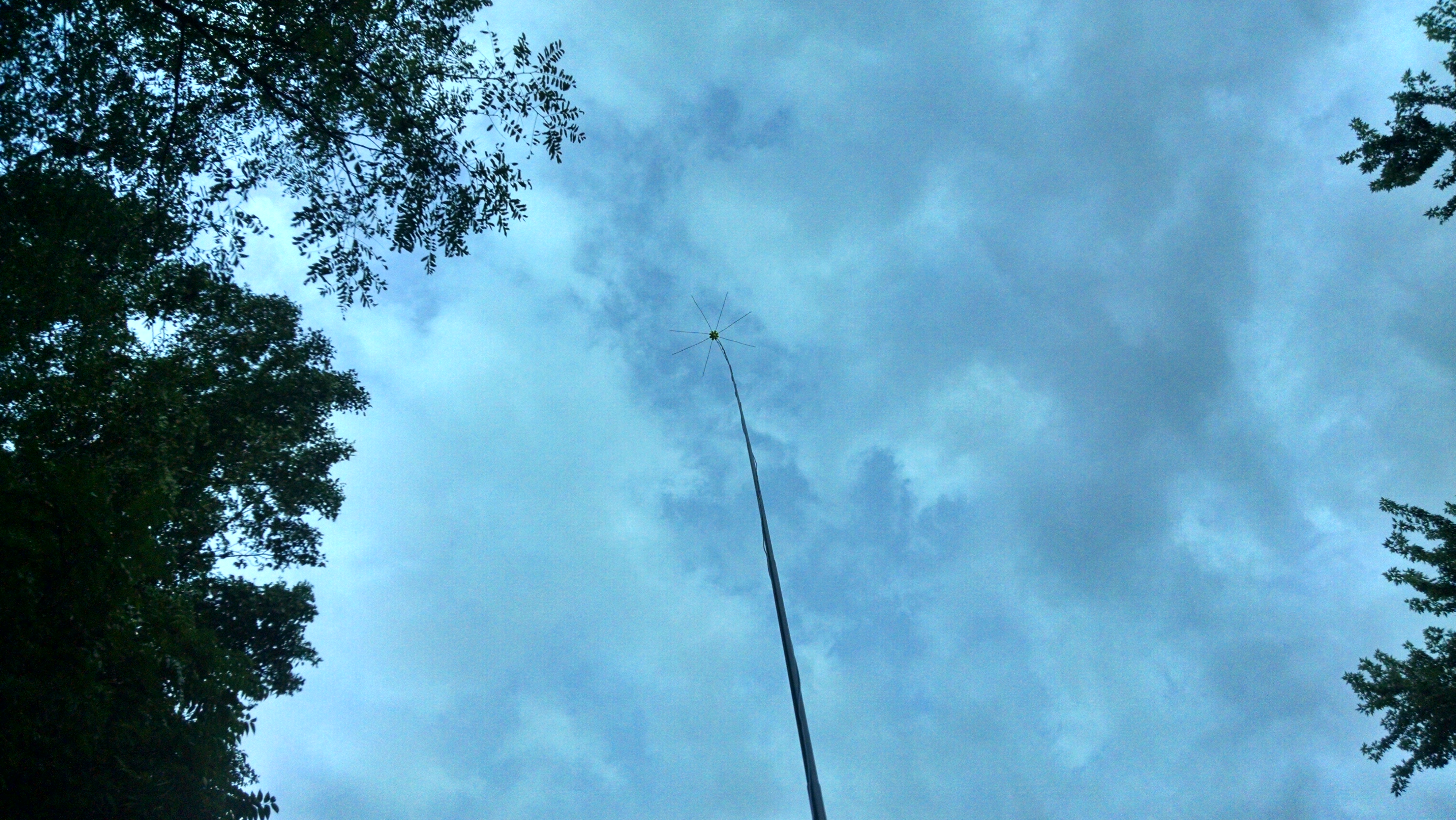
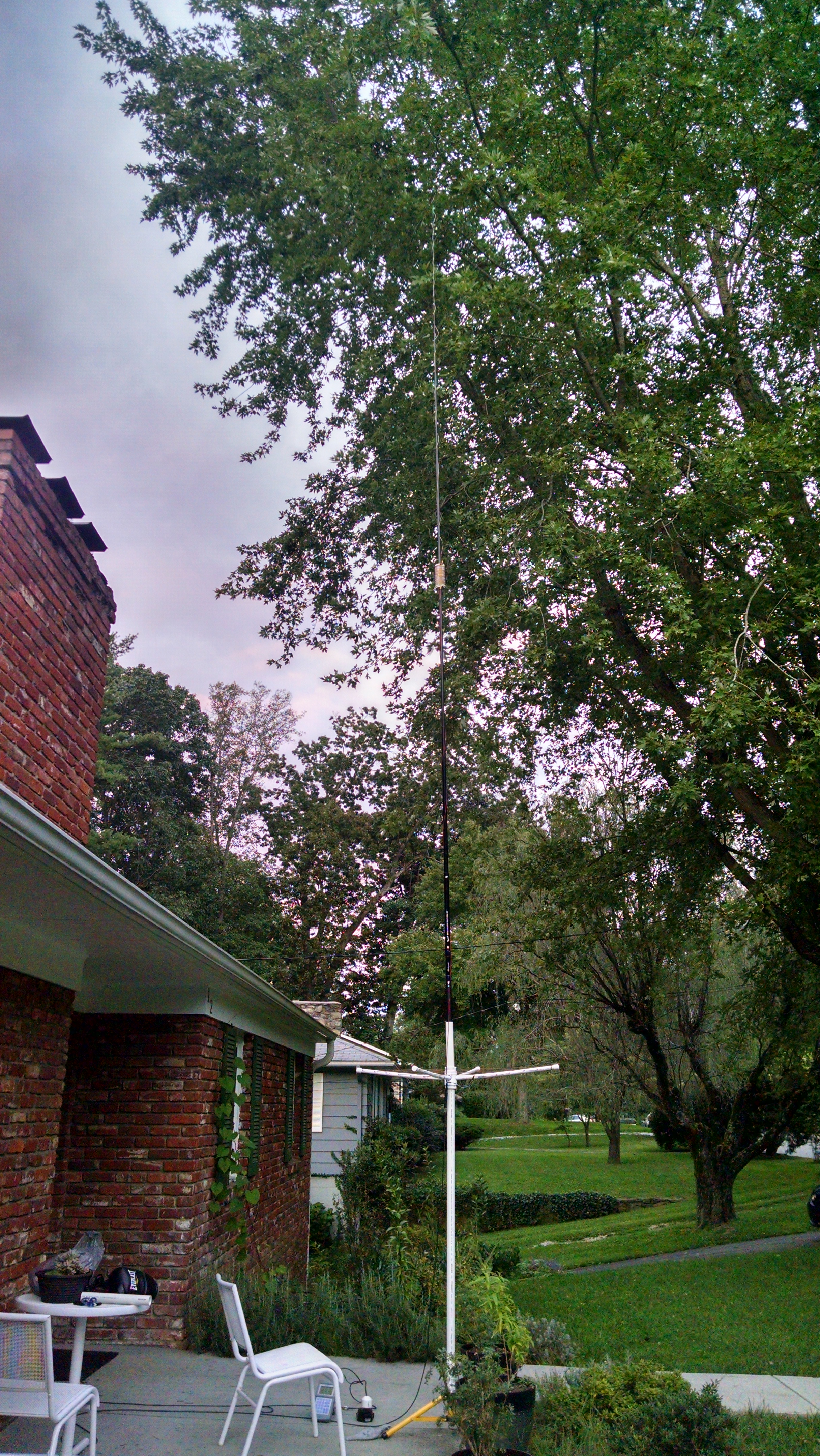
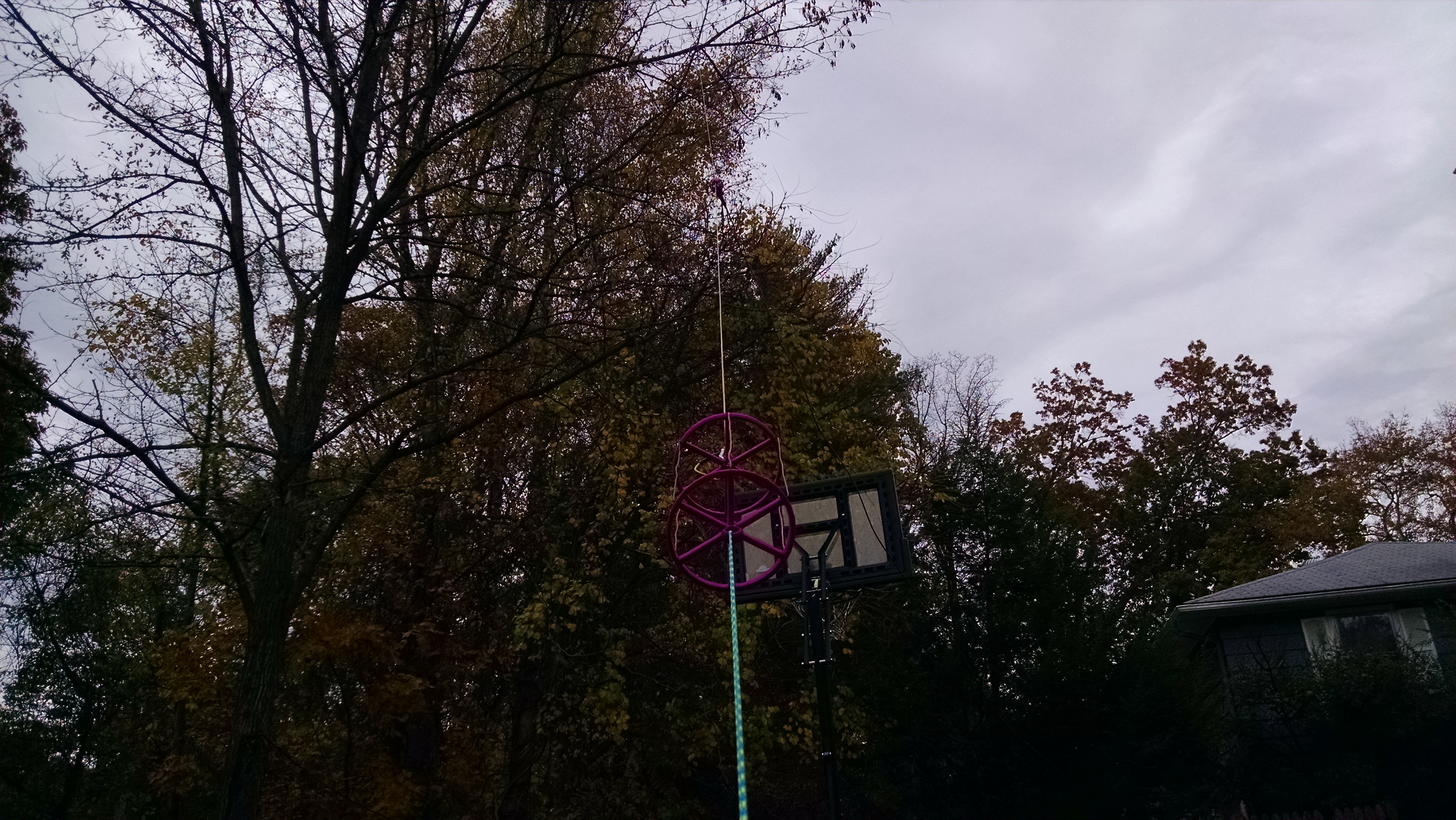
Antenna mounted as a sloper

IMG_20151031_165712056

The Loading Coil and Hat frames were printed on my 3D printer using a low RF loss plastic material – High Impact Polystyrene(HIPS). Here is a link to the STL files which can be used to print these forms. An STL file is the standard format used by almost all 3D printers. If you do not have a 3D printer – there are online services available to 3D print the files as well as some print shops and office stores. Other plastics could be used such as ABS but use HIPS if you can. Because the antenna is relatively small you can mount it vertically or nearly vertical with the center relatively high above ground for better efficiency so besides being small, the antenna has some benefits with respect to ground losses and radiation angle (depending on how you mount it).
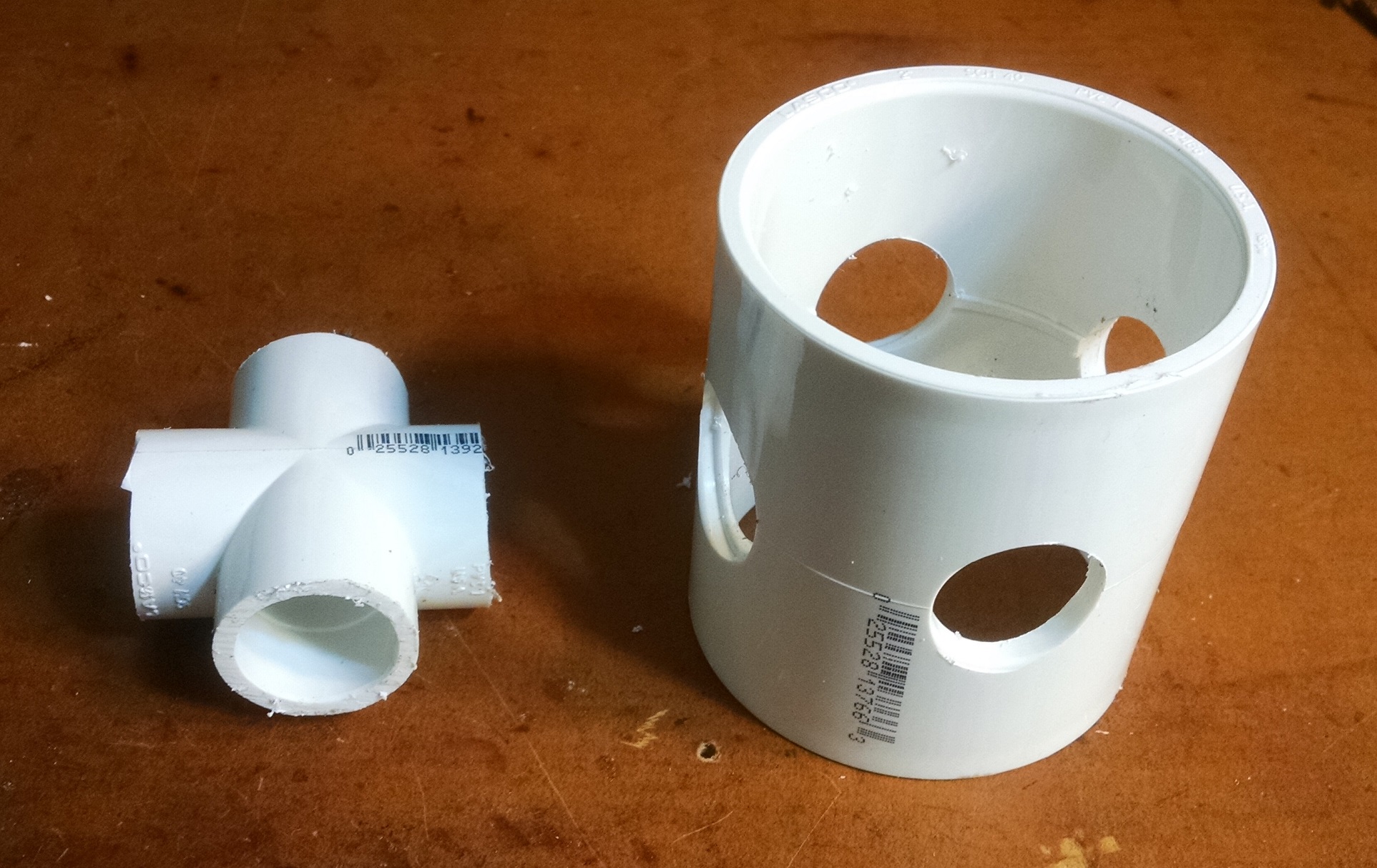
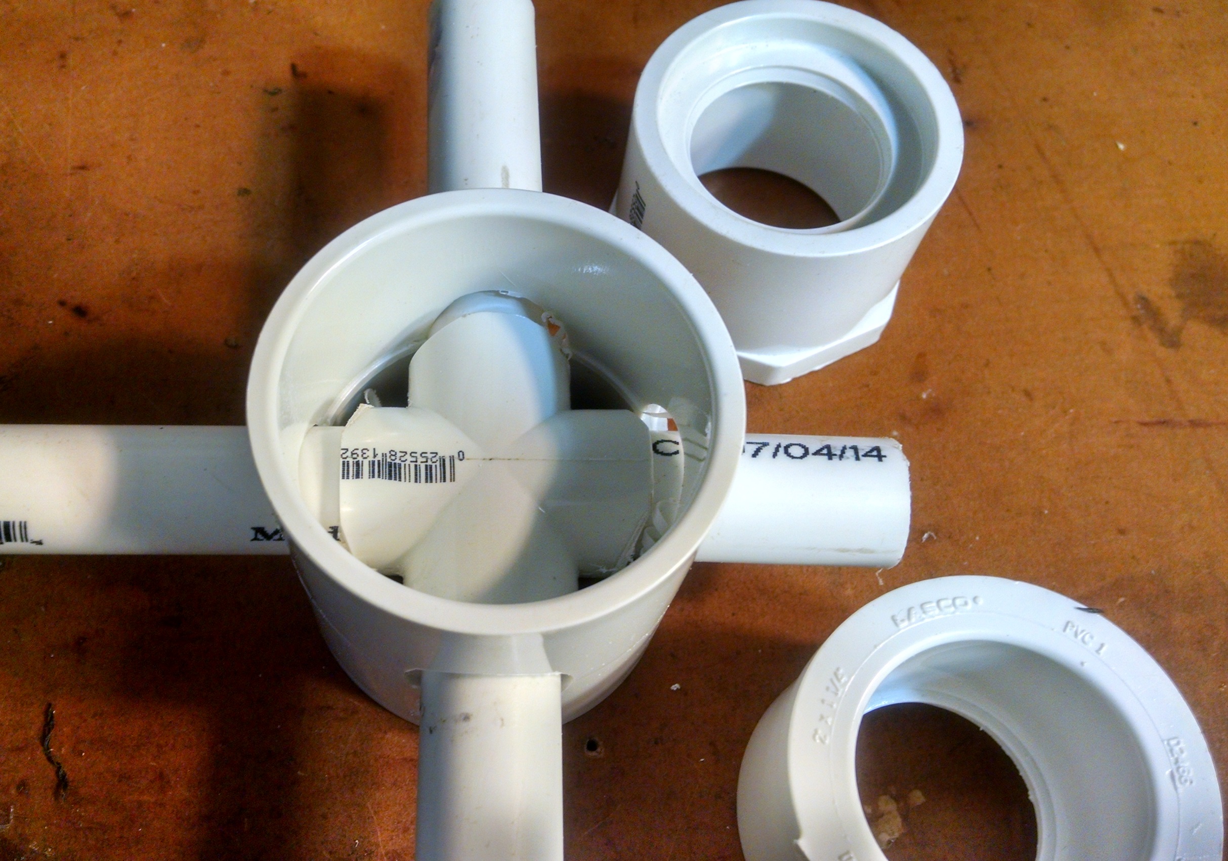
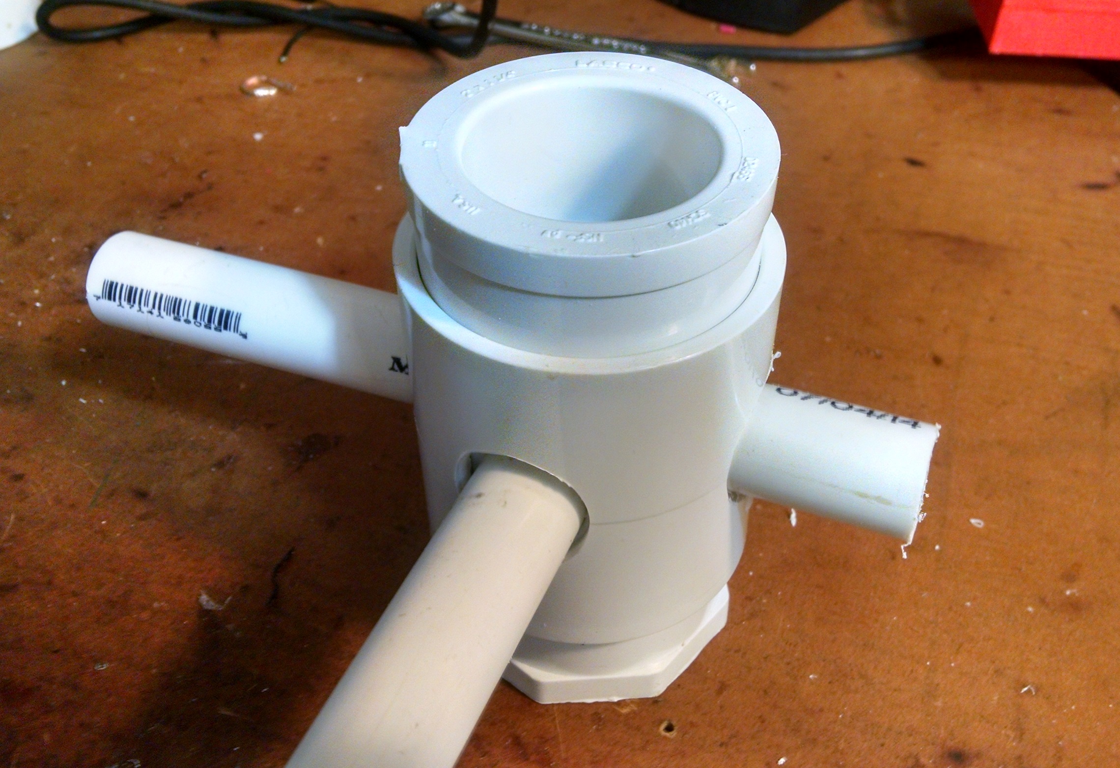
Loading Coil

Coil has 11 full turns(plus half a turn) to center from each side(3 inch diameter and 3/16ths turn spacing). It can use 12 gauge or smaller wire. The mounting holes can be tapped for 6/32 or 8/32 screws for the coil terminal and connector flange. Total coil inductance between 16-17 uH
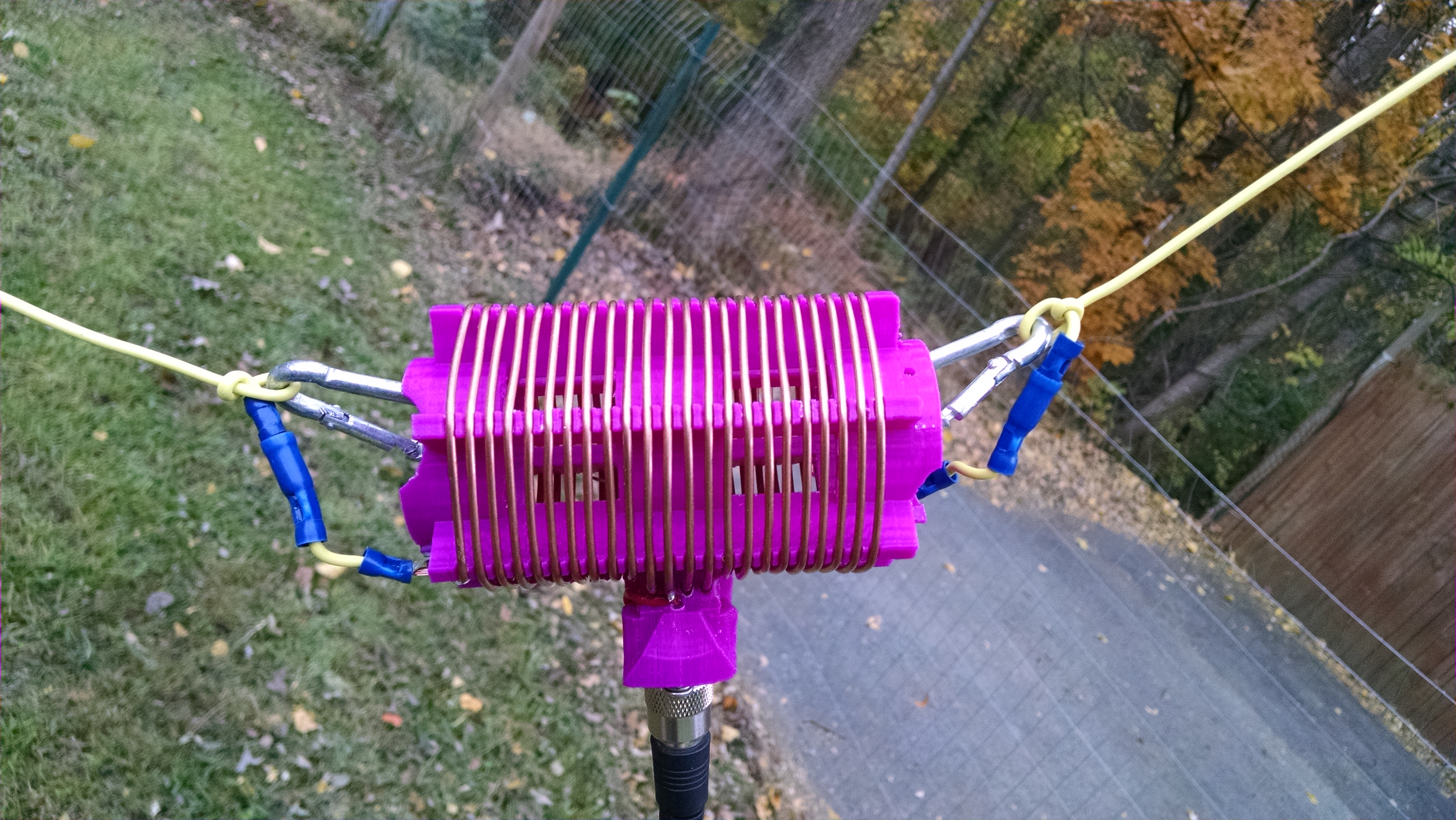
IMG_20151031_170006399 IMG_20151031_165858898

Capacitive Hat

The hats are 6 inches in diameter with the wire soldered together in the center and then pinned with a 8/32 screw and washer.

IMG_20151031_165650532

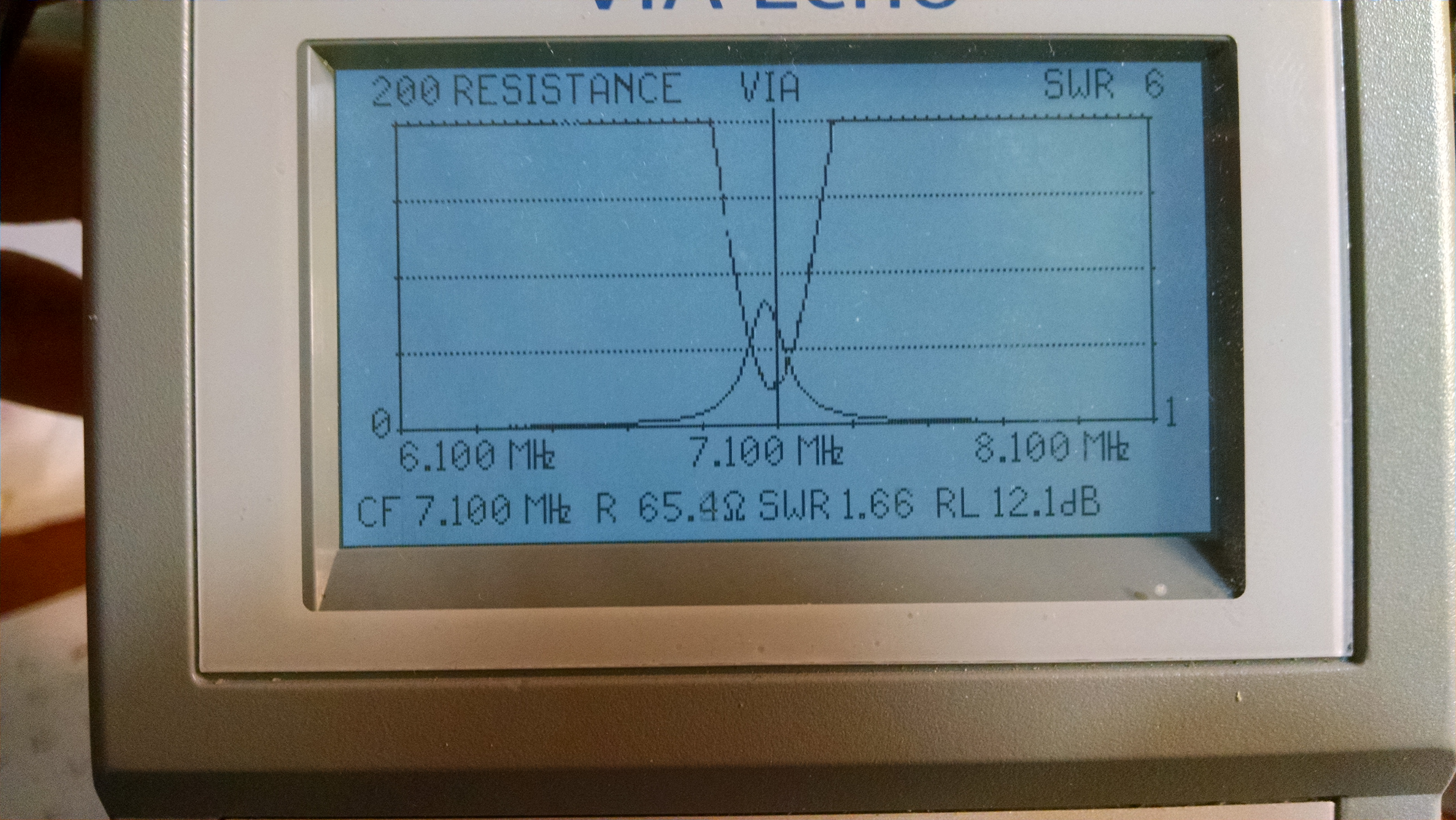
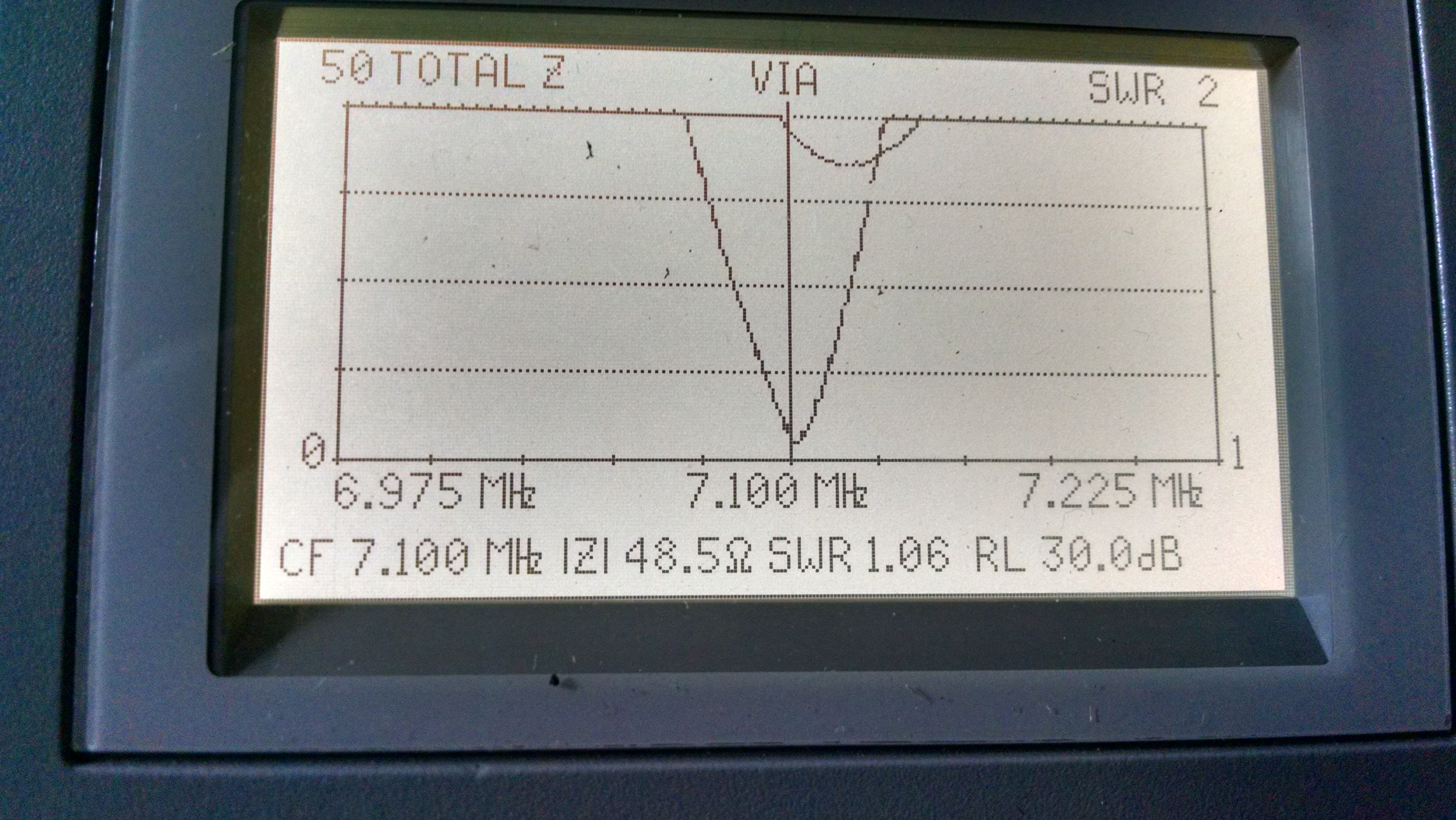
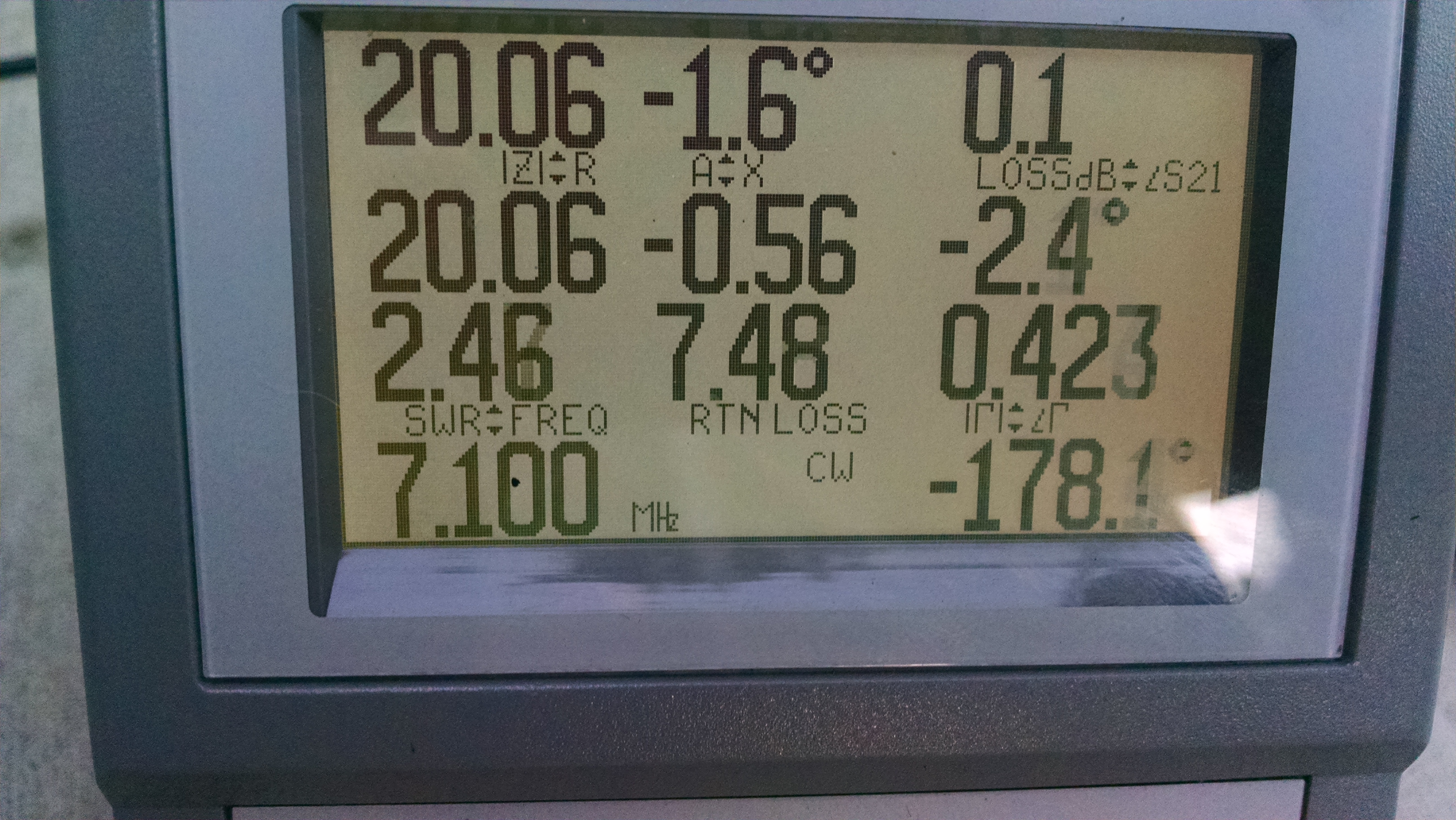
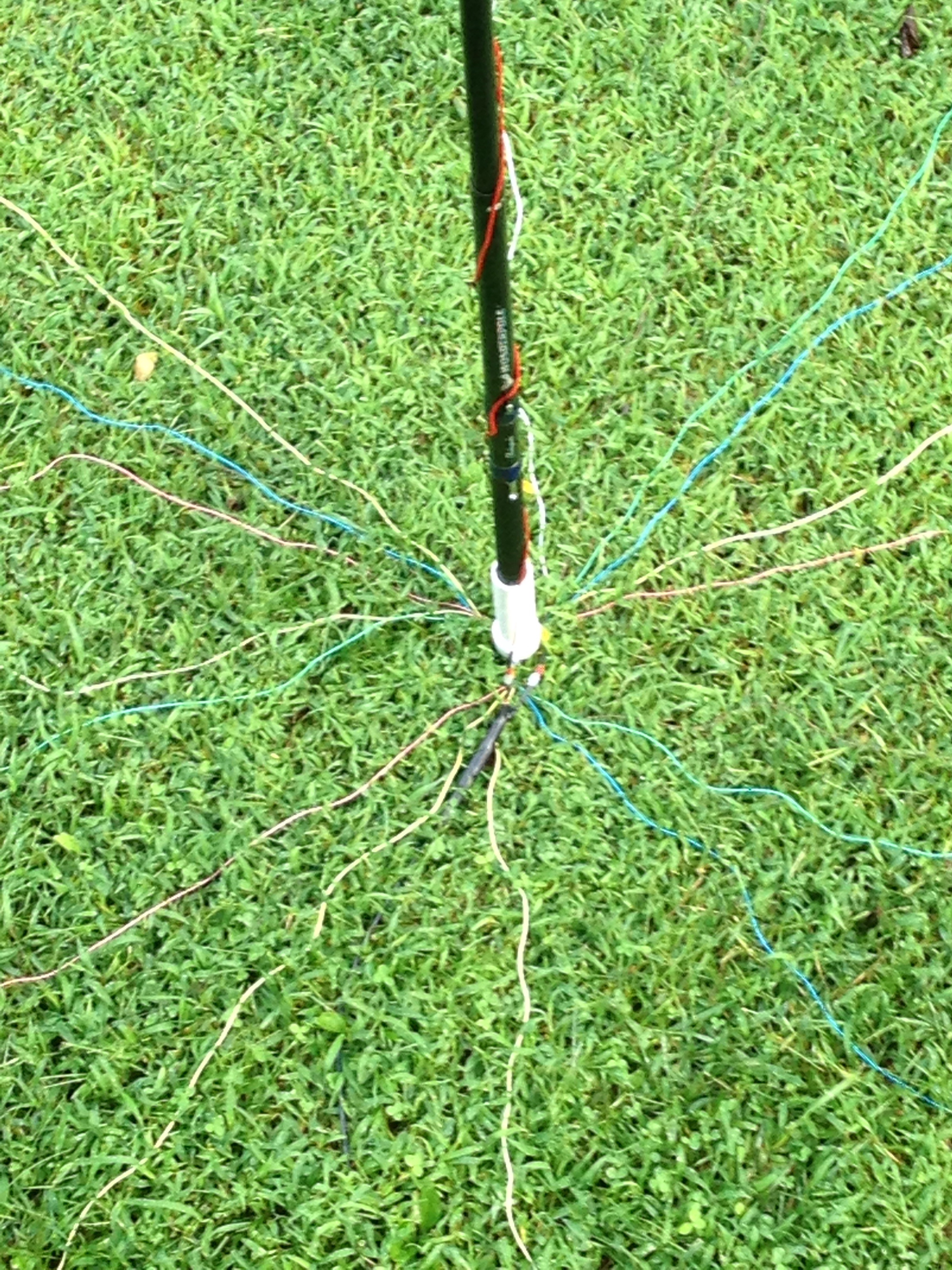
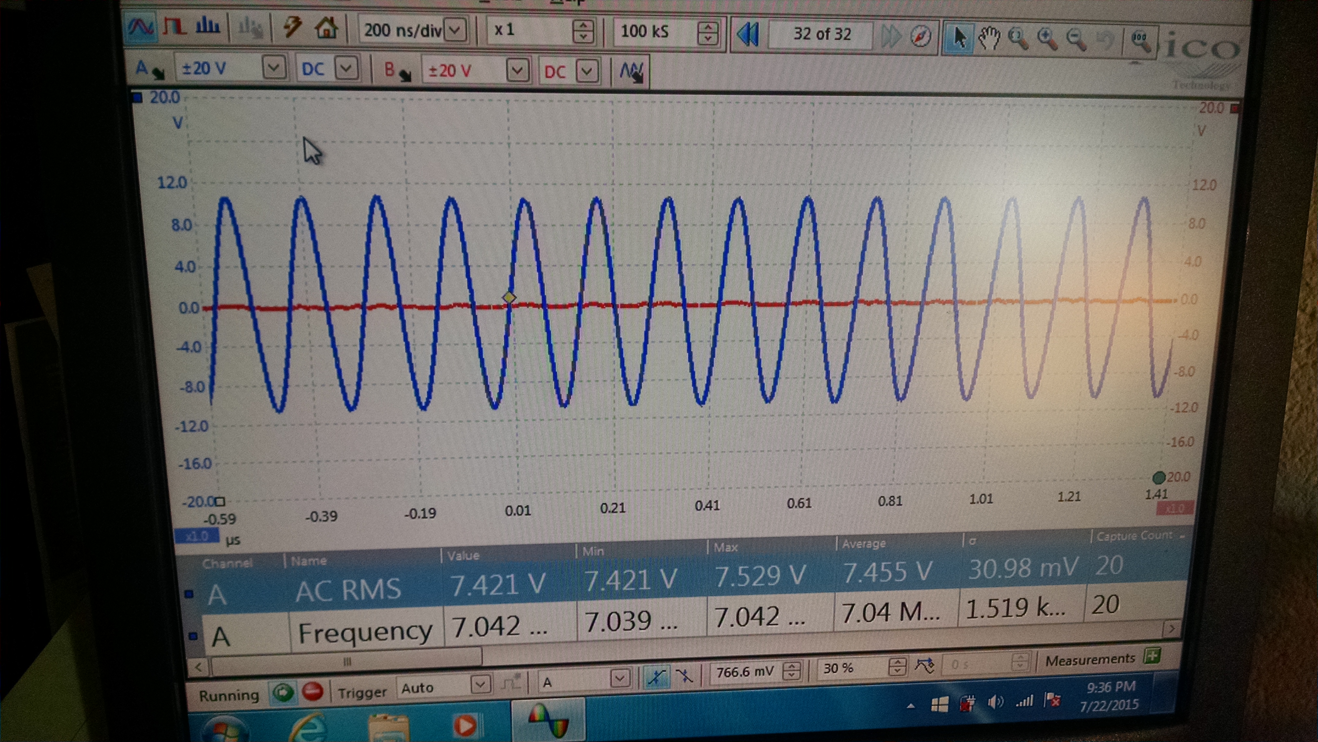
Antenna adjusted to resonance for 40 meter CW

IMG_20151031_170252197

Ultra Simple 8 pole Low Pass CW filter

I wanted to add more audio filtering to my 40 meter CW transceiver https://circuitsaladdotcom.files.wordpress.com/2015/08/qrpxcvr2.jpg  but didn’t want to put much effort into it, so I used a MAX7401, 8 pole switch cap filter IC. This IC requires just a few discretes and has an extremely low passband ripple and group delay, as it is a Bessel configuration. I have used this IC before in some of my guitar effects pedals. It has worked very well in my other designs. The knee of the filter is adjustable via a capacitor(C4). To integrate into my receiver, I simply connected the input and output of the filter across the input capacitor(C27 removed) connections to the final audio amp. It may be desirable to put a single RC low pass filter stage in series with the output of the switch cap filter to remove clk artifacts on the output.(clk is 100X greater than the roll off frequency). Performance is very good with clear tone and no ringing.

Below, I have a video demo of the XCVR utilizing the filter. This version of the XCVR is tuned via a POT connected to the microcontroller A2D converter instead of a rotary encoder. It also has a push button to shift in 5Khz increments. When the button is depressed for longer, the frequency in KHz is sounded in morse code. Only the KHz is sounded, so for 7.100 Mhz for example, only 100 is sounded in morse code. In the video you can also see my cool 3D printed Code Key. It uses rare earth magnets instead of a spring for key action. It’s a really delightful bug.

Picture of filter Daughter Board connected to XCVR

8polefilt

Filter Schematic

Simple CW filter

Video of XCVR using the Filter

More Spiral Experiments

I have come to the conclusion that my large(1 meter diameter) spiral loaded vertical is really an asymmetric dipole with the spiral being the other radiating element.  For fun I made a much physically smaller spiral and attempted to use that.

New Small Spiral

IMG_20151014_080952443

I found it was extremely difficult to tune and narrow band as well. It did work but the receive  level went down slightly  so I have concluded it is not  as efficient as the large spiral. Feedpoint impedance measurements were better matched(higher R) than the other spiral but this is surely IR loses in the dense coil.

My conclusion is a moderately sized spiral of a few turns(> 1/20 wavelength) is very effective as its area makes it a respectable radiator. If the spiral coil becomes small the approach doesn’t work so well.  My large spiral is a solid performer and it is my opinion that it is preferable to a modest radial array.

Vertical with Tuned Spiral Counterpoise – Updates

So I have been using the my center loaded 40 meter vertical with a spiral resonant counterpoise for a couple of weeks and can say it is performing as well (perhaps a little better) than with my 24 ground radials. I did some simple field strength measurements with a spectrum analyzer and pickup coil; at about five different positions and at various frequencies in the 40 meter band. I did this with the spiral version and with 24 ground radials. Comparatively, they were within a dB of each other. The spiral was about 1 dB better in three of the positions and both antennas were about the same in the other locations.  However, this was only the case when the spiral was adjusted properly(less than 3:1 SWR).

I improved my loading coil by 3D printing a low density coil form and added a capacitive hat to improve the performance of the radiator as much as possible

IMG_20150911_195109288_HDR IMG_20150911_195149153

The 2:1 SWR bandwidth is small (50KHz) and if you move it around you need to retune it -so its more critical to adjust and less forgiving than when radials are used. The footprint is much smaller though and I have easily set it up in my driveway, on my deck, and over grass (about 5 feet off the ground). Generally, I am achieving the same range, signal reports and number of contacts as before. Using the spiral decreased the bandwidth of the antenna and lowered antenna impedance, while using the same exact 1/4 wave element I was using previously with radials.

I created a simple L matching network for the antenna which works beautifully to convert the 20 ohm Z to 50 ohm at the feed point. You connect the coax ground to the spiral for resonance, then simply connect the L network ground connection to that same coax connection point. If not optimal, you can slide the L network ground connection  along the spiral wire a few inches on either side of the coax ground connection to tune. The values for the L network are .5uH and 470 pF. You don’t need the network if you can tolerate the higher SWR but it feels good to see such a nice match!

L Network used to match spiral               

IMG_20150906_193630496 IMG_20150906_193730190_HDR

Update: 10/05/2015

So I have done some more experiments with field strength and also done some research and found this is a topology that is a a variant of a spiral antenna. It has been coined the “spiralpole. Essentially I have created a vertical dipole where one half is the spiral element and the spiral is actually radiating significantly. This is particularly true because my spiral area is large and the number of turns is low. I had a feeling this was the case( the spiral was radiating). So the counterpoise is in fact now a radiating element. It seems to work. I plan on making a much smaller spiral coil and see what happens.

Short 40 meter Vertical with Tuned Spiral Counterpoise.

I took my 20 foot short 40 meter vertical and tried using a spiral tuned counterpoise instead of my 24  radials. The counterpoise is off the ground only about 5 feet so the antenna is still ground mounted.  Before I describe the details of the design. I want to discuss performance. With ground mounted radials I was getting a little over 50% efficiency. This is derived from a predicted feedpoint impedance of 18 ohms, but measured impedance being 31 ohms(13 ohms of losses). Using the spiral counterpoise; the feedpoint impedance is about 21 ohms – which implies >  80% efficiency. The only draw back is the tuning is a critical with about 6 inches difference between un-usable and perfectly aligned. As a practical approach, I made the spiral a little long and then I adjusted my coax ground connection point- to tune the antenna. I have made no effort to match perfectly to 50 ohms and the SWR is 2:1- over about 100 KHz. Tuning need only be adjusted when using a different portion of the band or moving physical position is some significant manner(placing lower to the ground for example). Regardless, there will only be about 6-8 inches of adjustment ever needed to tune the antenna. A  L network or broadband transformer may be desired, to match to 50 ohms. Adjusting the feed point up the antenna a little, should also work to get a better match. The counterpoise appears to work very well and I can recommend it as an alternative to radials. I am assuming the radiation pattern is the same but I have not evaluated this. Of course making contacts is not a  good measure of antenna performance but I have made  contacts using the antenna in this manner -so it certainly works. Based on my measurements, it has less loss using the spiral counterpoise vs ground radials.

Short Vertical  Tuned Antenna Impedance with Spiral counterpoise

20 ohm Z with almost 0 reactance (-1.6 deg)

IMG_20150831_195215062

Tuning the antenna element to resonance first (using a dinky ground plane…or a good one!) is prudent, because it is very tricky to simultaneously tuned the antenna and the counterpoise. Once the radiating element  is tuned correctly, tuning the counterpoise is  straightforward. I just a have an alligator clip to shift the ground connection point on the counterpoise.

Completed Counterpoise installed and tuned

IMG_20150831_195256410

Complete Antenna

IMG_20150831_195511386_HDR

The counterpoise is  a large square coil made on a 1/2 inch PVC frame. Four legs of 1/2 inch PVC (each leg is about 21 inches long) are connected by means of a four-way coupling which is pinned within a drilled 2 inch coupling. A piece of 1-1/4  inch PVC pipe is used to hold the fishing pole mast on the top and provide a means to mount on the ground. 2″ to 1- 1/4″ reducers are glued into the 2″ coupling. The entire coil is 5 and 3/4 turns spaced at 3 inches between turns. The turns start at 5 inches from the center. I measured  3 inch spacings on one leg and then did the same on the other three other legs. On the other legs however, I shifted the 3 inch point forward 3/4 of an inch on each leg with respect to the previous leg in the the winding order. This way the wire gradually shifts outward without abrupt turn hopping. I used #12 bare wire -you will need at least 40 feet of wire to make the coil.

four way PVC coupling and drilled 2 inch coupling

(the four way has to be trimmed 1/8″ on the ends to fit)

IMG_20150830_163035473

Coupling held in place with 1/2 inch stubs

IMG_20150830_163825709_HDR

1 1/4″ reducers are press fit and glued into the 2″ coupling

IMG_20150830_163840084_HDR

Efficient Portable Ground Mounted Vertical Antenna for 40 Meters

I like to work QRP CW and exclusively use  home brew portable equipment. I have struggled with the best antenna to use for 40 meters.  Wire antennas are lightweight and usually efficient but often require tuning, a structure or tree to install, and often end up low to the ground with poor DX performance. A 1/4 wave vertical is a good choice but is 33 feet long and requires lots of radials for acceptable efficiency.

What I came up  with is nothing new but I was able to verify good performance and efficiency.

I have constructed  a center loaded  20 foot vertical using a 20 foot collapsible fishing pole as the mast. The loading coil is wound with 12 gauge bare copper on  a couple of PVC 2 inch couplings joined together. The coil is about 12 uH in value. Final tweaking is accomplished by creating a tiny loop at the top of the antenna(2 inches of area) that can be varied in size(create a small amount of capacitive top loading). The radial system consists of 21 ten foot radials. Since they are short the footprint is small and setup is easy. Using more short radials is more efficient than using a few long ones(up to a point). Unless you are going to use 60 radials or more there is no reason to have them 1/4 wavelength long. This is because current density is greatest  at the feed point and diminishes as the radials extend out. Roughly, 24 radials at 1/10 wavelength long have the same performance as the same number of radials at 1/4 wavelength long.

From my measurements with a network analyzer, the resonant  feed point impedance is 30 ohms and calculated impedance with zero losses would be 18 ohms. So its on the high side of 50% efficient, which is good for a portable vertical.

I have made a couple of cross continent contacts with good results using 1 watt, so I am pleased with the ease of install, small footprint, portability and effective radiating.

Antenna stuck into my Yard

image (2)

Close up of the loading coil

image (3)

Short Radials at Base

image (1)

40 meter Direct Conversion QRP Transceiver using 74AC240 Power amp

This is my new qrp transceiver design. It uses the CS2000 clock generator circuit I use for a number of my receivers and a 74AC240 buffer as a push pull 1.5 watt final amplifier. The final unit uses my low power/low noise LCD display and is set to tune from 7.000 to 7.300 MHz.

https://circuitsalad.com/2014/07/31/very-low-power-3-digit-lcd-display-with-serial-control/

If one changes the the output networks (L matching and half wave low pass) and simply adjusts the software for tuning range, one can use any band desired. The inductors are air wound or made using scraps of ferrite taken from junk box inductors. Tuning is accomplished by means of a cheap mechanical rotary encoder. The Micro-controller provides the control signals for T/R switching, generates a sidetone and shifts the frequency 700Hz on TX. The transceiver supports full break-in keying. The input to the receiver is isolated during TX by means of a BSS123 mosfet used as a switch. A 2N7000 will work here as well. The receiver uses a leftover inverter stage as a RF amp. It works surprisingly well and also provides the bias for the switching mixer input. There is a 2nd order op amp low pass filter for CW. The coupling capacitor C30 is normally not needed for receive, but when the TX is keyed, there is DC imbalance on the output of the mixer switches – the differential audio amp will slam to the rails creating large key clicks on the side tone. C31 is required for stability when keying, without it, occasional parasitic oscillations can develop.

The circuit could be easily modified to use a VXO or VFO. One would simply have to modify the keying logic(connect key directly to TXRX signal and invert this signal for MUTE connection) One can use the remaining two 74HC04 inverters to generate a side tone and the the logic.

Update: Changed the band to 30m for fun. The only hardware changes were: L1 & L2 (.11 uH), C21 (800pF), L3 (.6uH), C22 & C23 (270pF). The 74AC240 works beautifully at 10 MHz – outputting the same 1.5 watts and even running  a few percent more efficient. I must have nailed the matching network values.

Schematic(minor edit for key clicks 8/18/2015)

QRPXcvr

Unpopulated Home Brew board

IMG_20150730_144829565

Populated board

IMG_20150806_163351717

XCVR in Home Brew 3D printed Case

IMG_20150810_111619507

IMG_20150810_111515266

Video Demo

1.5 Watt 74HC240 QRP RF Amp using 74AC240 inverter for improved output

I am building a little QRP  rig for the 40 meter band , utilizing one of my DC receiver designs. I am using a CS2000 clk generator for the receiver and can use the clock output to drive a 1 watt or so RF amp for the TX. I am prototyping the transceiver now and will post that  design when it’s done. I designed a nice class E final at about two watts but it was tricky to test and tune…etc- so I thought I would come up with an amplifier that was easier to duplicate by other builders. This amplifier works well and is easy to build. It puts out in excess of one watt from a single  74AC240 (the 74HC240  will also work but not put out as quite as much power). You can also use a couple of 74AC04’s  also. The 240 is convenient however, because it has an enable pin for keying when using CW. The circuit uses two sets of four inverters driven by  a couple more inverters( to create differential inputs) and either a balanced L network(followed by a balanced to single ended combiner transformer) or  a LC tuned balun to match the output to a 50 ohm load. The schematic shows both methods and values for 7 Mhz. I have created a spreadsheet for calculating networks for any band desired. The inverters have very low impedance and so you need to match roughly 4 ohms at the inverters to 25 ohms for each side of the push pull sets. You need to heatsink the inverter IC’s! I used a  small heatsink for IC’s (seen on top of the 74AC240 TSSOP package) but you can use a piece of bent aluminum – or copper, etc. Because of the low Z, all of the matching inductors are small – so you can easily fabricate your own small  air wound coils or coils wrapped on scraps of ferrite from junk inductors- you don’t need to have specialized toroid cores.

The LC balun works well but was trickier to get adjusted (needed further matching by means of a L network). The simple “sortabalun” transformer  combiner in tandem with the balanced L network works  a little better and  is easier to design and  adjust. The only disadvantage is you need some sort of ferrite core material for the transformer – whereas the LC balun method can be all air inductors. If you have some ferrite material – use the transformer method. One could do impedance transformation with the transformer but the L matching provides filtering, can be easily adjusted for  parasitics in the inverters(capacitance) and  a 1:1 transformer is very easy to construct!

The only drawbacks of this design are, one; you can only use 5v up  8V max to power the amp and two; it is not very efficient (mine runs at about 40%- 45%). It can draw .4 amps @ 8V – which is quite a bit of heat! Having said that, it is fun to build and tolerant of mismatched SWR. Overall, not bad performance. If you used two of them (8×8 push pull) you would need to adjust down the L network inductors and increase the capacitor(this lowers the impedance at the inverters further). I expect you could get more than 2 watts.

Schematic Diagram(minor revision 07/29/2015) 

QRP RF Amp

View of main amp using LC Balun

 IMG_20150722_213556201

 Just over 1 Watt 2nd and 3rd harmonic down 37 dB with LC Balun

IMG_20150722_213704057 IMG_20150722_213722665

Over 1.5 watts with balanced L network and sortabalun!

Harmonics down more than 40 dB!

IMG_20150723_193630353 IMG_20150723_193652596

Link to network designer spreadsheet: https://www.adrive.com/public/5wtBBr/network%20designer.xlsx

Software Defined Radio baseband processor based on FV-1 chip. NO COMPUTER required!

There is this great DSP processor chip  called an FV-1 which is a  dedicated audio dsp processor  sandwiched between stereo  24bit ADC’s and 24bit DACs. It can be treated as a black box analog part with audio in and audio out only. With a few discretes, a crystal, and an eeprom, you can  create a complete Software Defined Radio processor the size of a couple of postage stamps. The input should be I and Q baseband signals. I have also been able to demodulate AM by phase shifting the I signal at audio as the information is symmetric about the carrier. IMG_20150618_122603733

I have developed a complete radio design, including: the Quadrature DC receiver, and the baseband dsp processor. I have AM mode, LSB and USB. I have included bandwidth filtering for the different modes and dsp AGC limiting. I am very pleased with the performance.

The FV-1 is programmed with a free compiler provided by Spin semi…the manufacturer. The FV-1 requires an eeprom to hold the programs and you can store up 8 selectable program blocks and each can have a different program function(such as my AM, USB, LSB modes). FV-1 parts and the dev board can be purchased at:

http://www.experimentalnoize.com

The FV-1 uses a very cryptic assembly language to create digital filters and perform signal processing. The commands include multiple operations all at once, such as multiplications, additions and reading writing memory. Each command is a building block for different filter structures and operations. You can execute 128 instructions per a sample and because of the efficient command structure you can create most single order filters in two instructions. There are a number different approaches to making allpass filters. One approach only requires two instructions per a filter section and uses FV-1 delay memory. I chose to do a different filter architecture requiring more instructions and more memory. It works well but the two instruction method works fine also. The FV-1 is very well documented and there are numerous coding examples. With a little  effort, reading through all the documentation, one can get up and running with FV-1 development pretty quickly

Example AM  demodulator and USB demodulator code for the FV-1 (quadrature inputs)

AM_Demod  USB_Demod

I program the eeprom with my microchip pickit2 programmer or the FV-1 dev board. If you are going to explore algorithm design with the FV-1, I would recommend getting the FV-1 Dev board. Below is the source code and hex file for my design such that one can just program the eeprom and use what I have done, as is.  Once loaded on the eeprom, the three modes AM, USB and LSB are selected by pulling to ground: Sel1, Sel2 and sel3 respectively. This code is intended for quadrature inputs to the left and right input channels and the output is on the right channel out (the schematic below combines outputs of the left and right DAC so you should probably load the output into the left DAC as well).

Link To FV-1 Hex file:

https://www.adrive.com/public/GNPAt8/SDRadioV1.hex

DSP processor Schematic(minor update to TDA7052AT 07/01/15)

dsp radio baseband

Basic Quadrature Direct Conversion radio

This is a variation of my last sampling receiver (link below)

https://circuitsalad.com/2014/07/31/simplified-switching-mixer-dc-receiver-uses-no-tuned-circuits

IQReceiver

allpass filter Calculator for IIR digital filter coefficients

allpass digital calculator

Quick Demo of USB..LSB…and then AM

Demo of AM from I signal only(no quadrature)

Code for AM demodulator with single signal input, (uses two instruction allpass filter structure)

AM_no IQ

Yet another Variant of the Junk Box Regen – this one is really weird but is an excellent performer

In this version, I removed the darlington detector and added a emitter follower(Q3) to bias Q1 and act as a reflex detector. With this arrangement the circuit works best with a supply voltage from one to two volts or so. I used three diode drops in series to achieve this. You could also use a LED.  It has extremely smooth regeneration. The selectivity is excellent.

Again I got it to work with a wide range of values, so it should be easy to reproduce. I hope someone builds this and gives me their opinion on performance.

Schematic (revised 07/01/2015)

2222A regen_rev3