Vertical with Tuned Spiral Counterpoise – Updates

So I have been using the my center loaded 40 meter vertical with a spiral resonant counterpoise for a couple of weeks and can say it is performing as well (perhaps a little better) than with my 24 ground radials. I did some simple field strength measurements with a spectrum analyzer and pickup coil; at about five different positions and at various frequencies in the 40 meter band. I did this with the spiral version and with 24 ground radials. Comparatively, they were within a dB of each other. The spiral was about 1 dB better in three of the positions and both antennas were about the same in the other locations.  However, this was only the case when the spiral was adjusted properly(less than 3:1 SWR).

I improved my loading coil by 3D printing a low density coil form and added a capacitive hat to improve the performance of the radiator as much as possible

IMG_20150911_195109288_HDR IMG_20150911_195149153

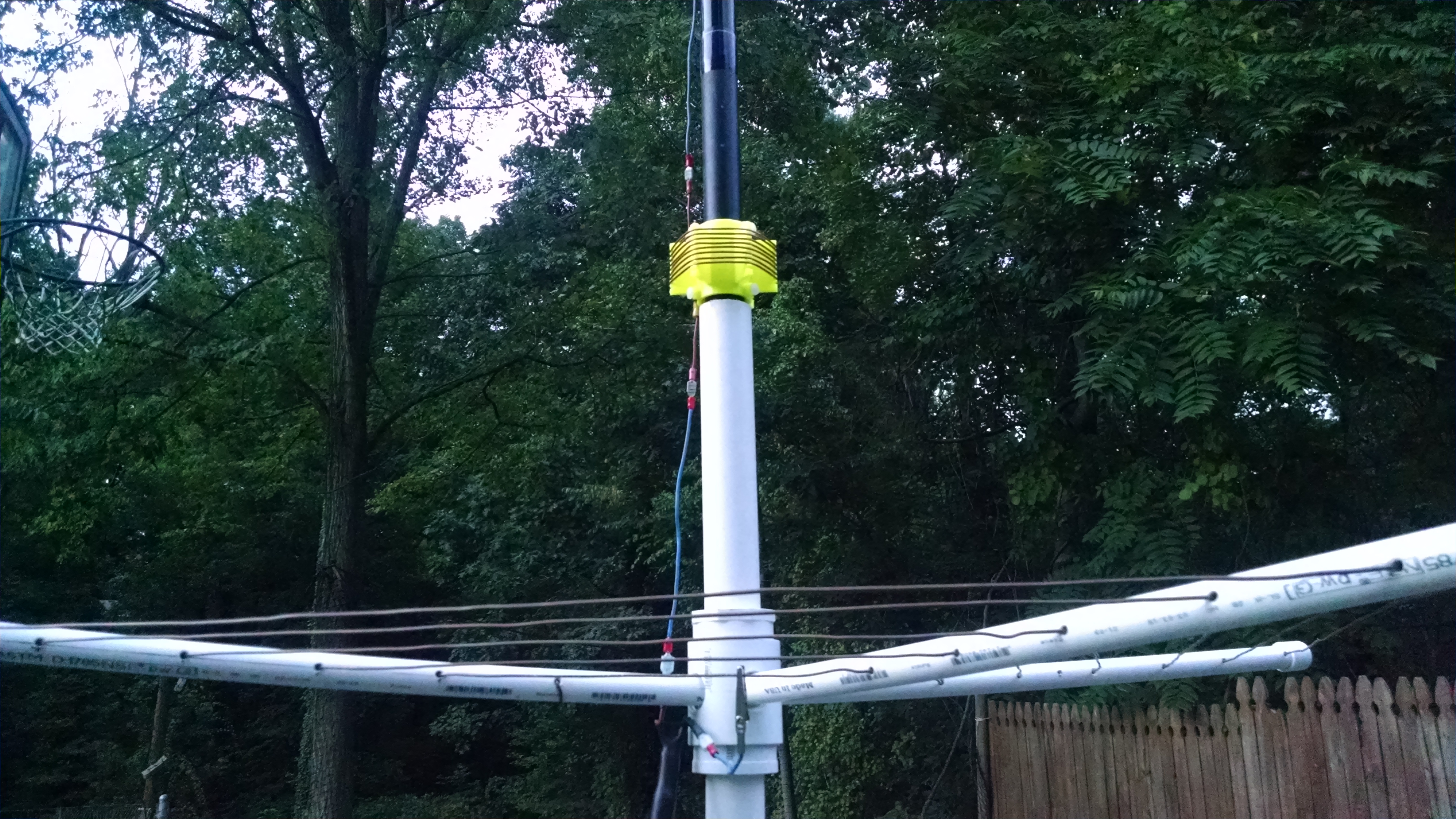
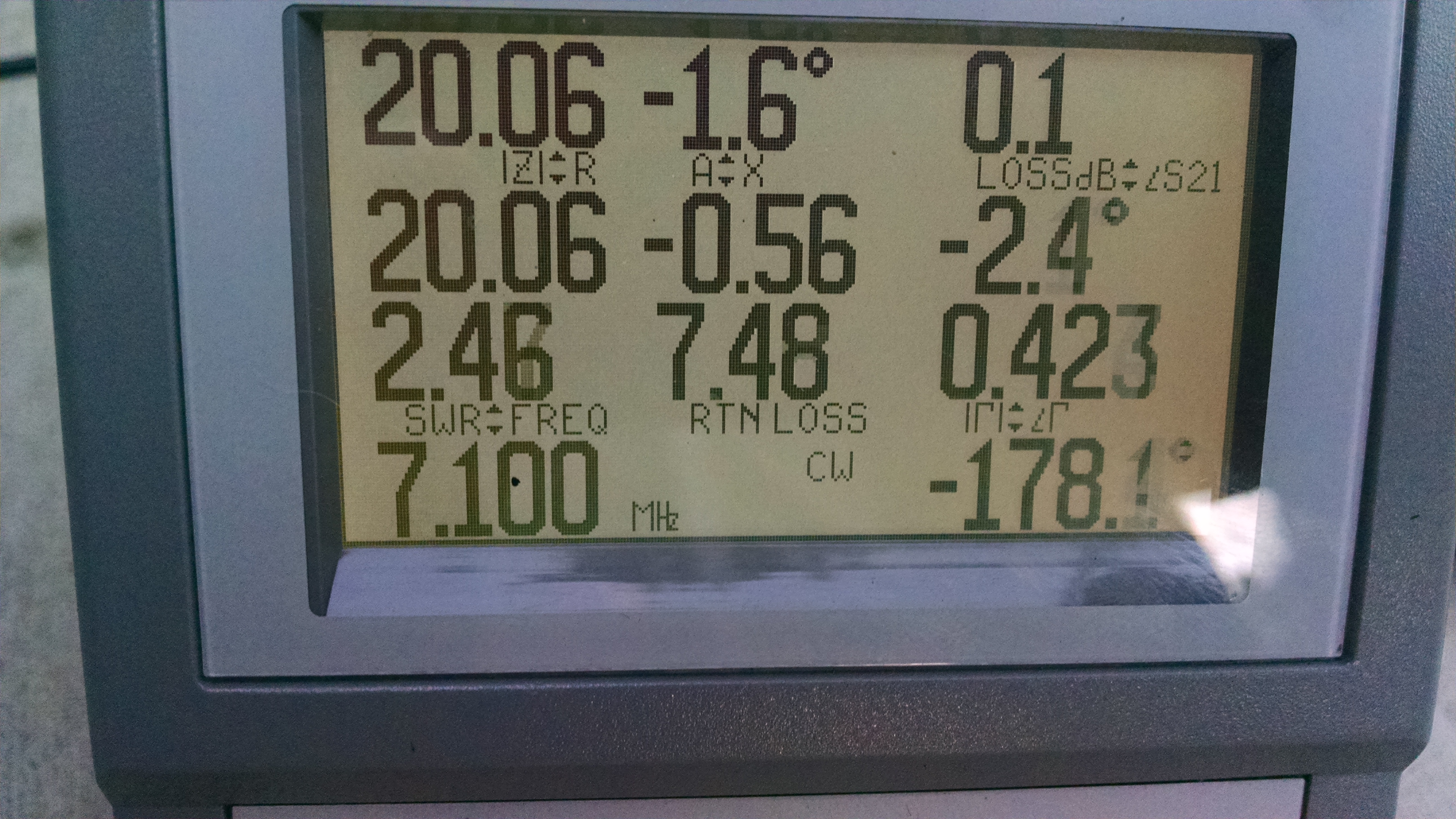
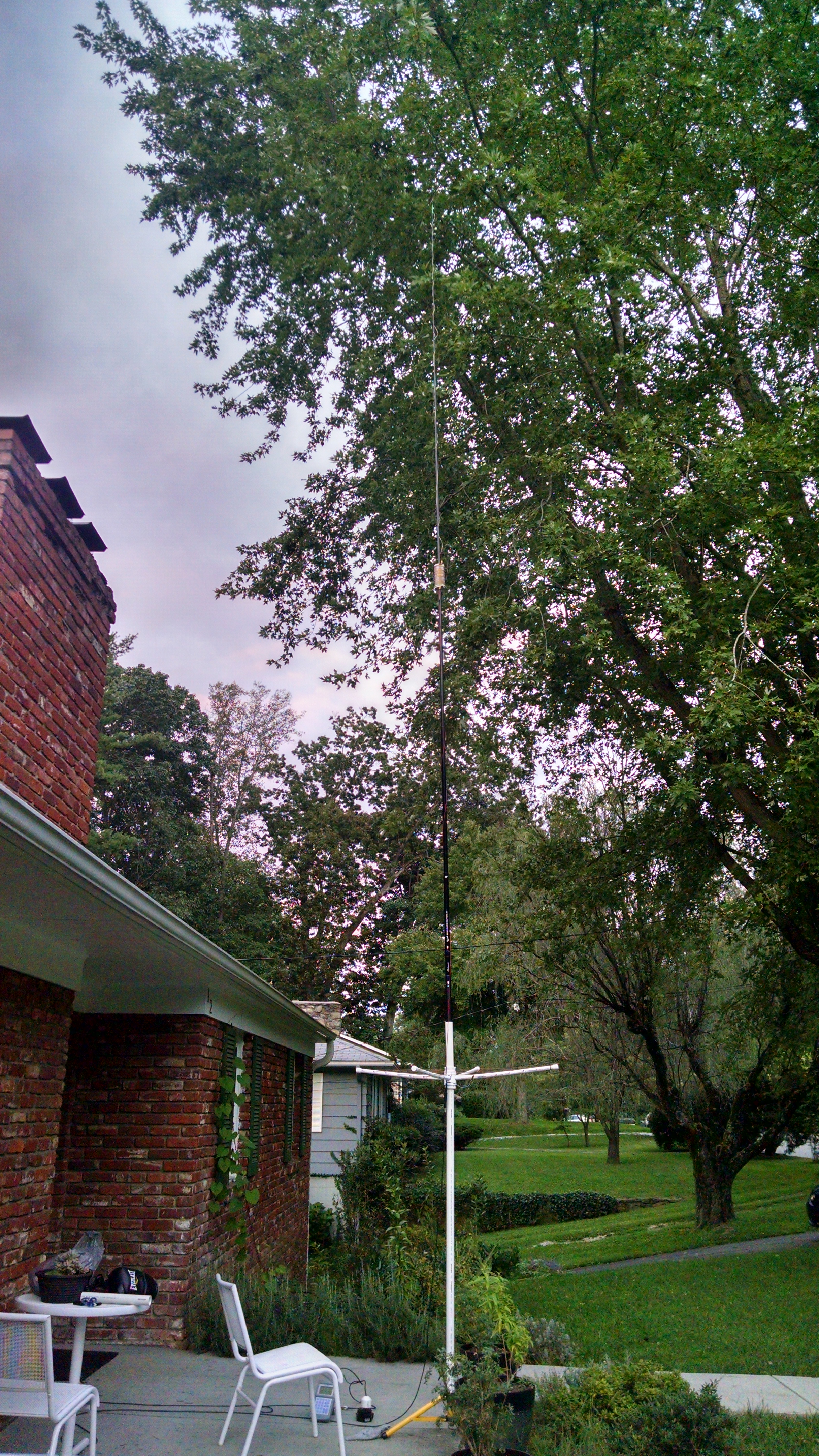
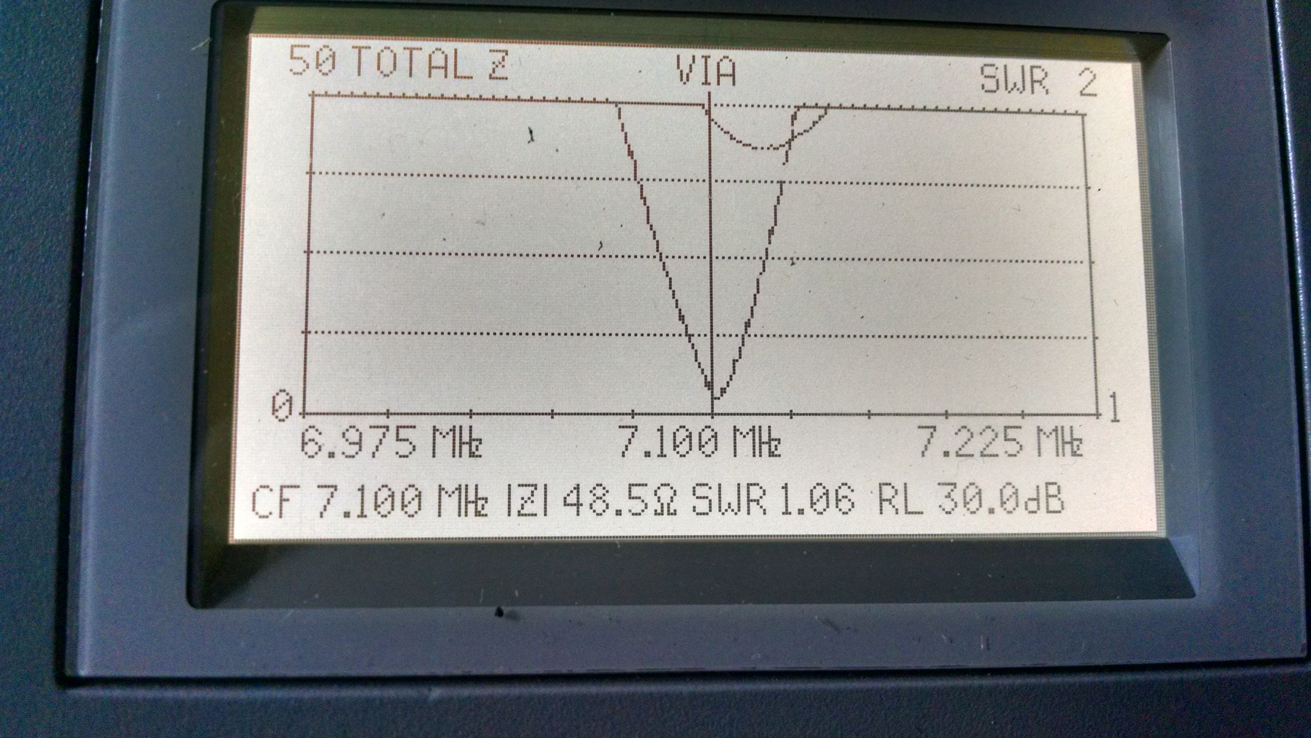
The 2:1 SWR bandwidth is small (50KHz) and if you move it around you need to retune it -so its more critical to adjust and less forgiving than when radials are used. The footprint is much smaller though and I have easily set it up in my driveway, on my deck, and over grass (about 5 feet off the ground). Generally, I am achieving the same range, signal reports and number of contacts as before. Using the spiral decreased the bandwidth of the antenna and lowered antenna impedance, while using the same exact 1/4 wave element I was using previously with radials.

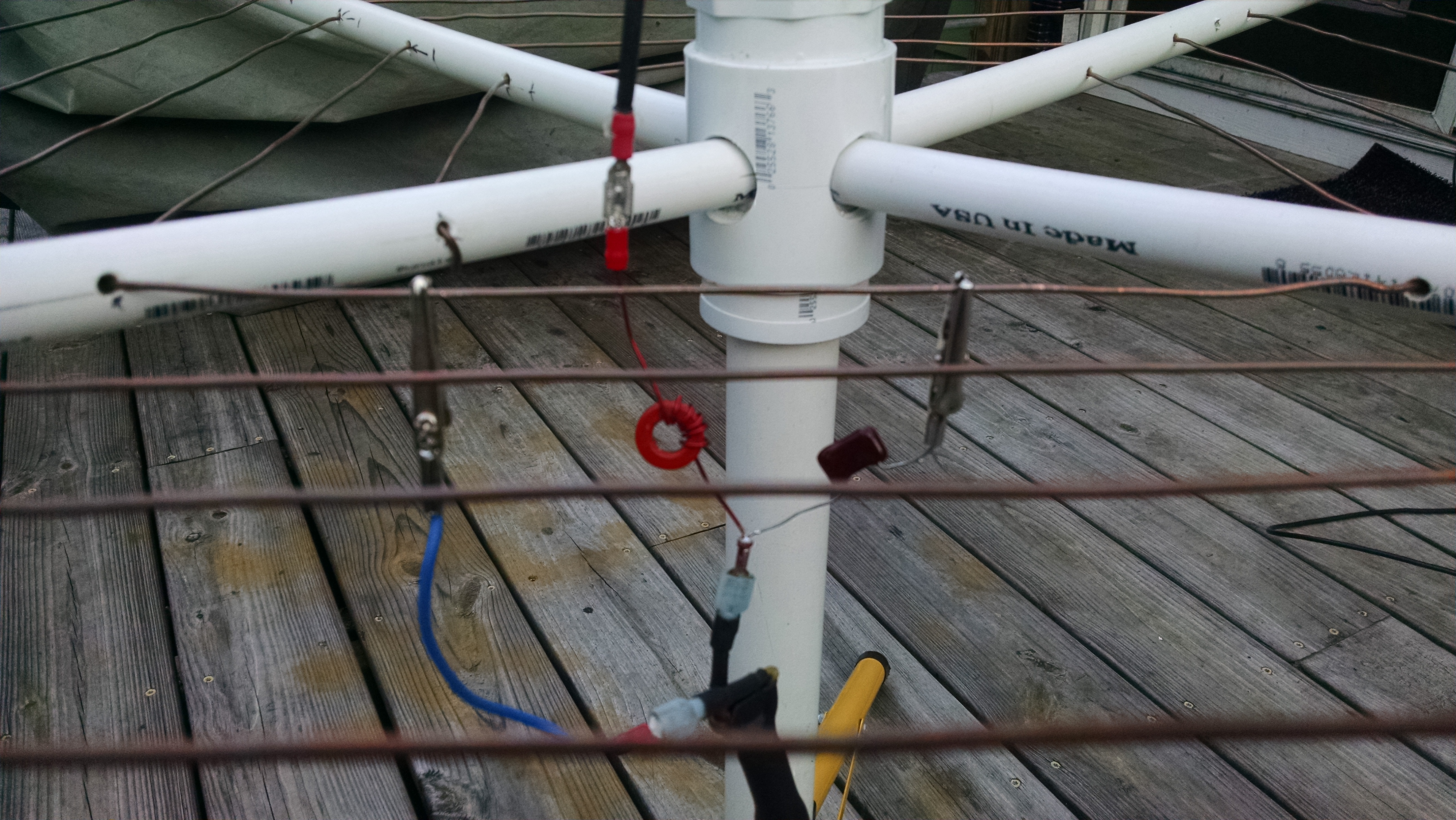
I created a simple L matching network for the antenna which works beautifully to convert the 20 ohm Z to 50 ohm at the feed point. You connect the coax ground to the spiral for resonance, then simply connect the L network ground connection to that same coax connection point. If not optimal, you can slide the L network ground connection  along the spiral wire a few inches on either side of the coax ground connection to tune. The values for the L network are .5uH and 470 pF. You don’t need the network if you can tolerate the higher SWR but it feels good to see such a nice match!

L Network used to match spiral               

IMG_20150906_193630496 IMG_20150906_193730190_HDR

Update: 10/05/2015

So I have done some more experiments with field strength and also done some research and found this is a topology that is a a variant of a spiral antenna. It has been coined the “spiralpole. Essentially I have created a vertical dipole where one half is the spiral element and the spiral is actually radiating significantly. This is particularly true because my spiral area is large and the number of turns is low. I had a feeling this was the case( the spiral was radiating). So the counterpoise is in fact now a radiating element. It seems to work. I plan on making a much smaller spiral coil and see what happens.

Short 40 meter Vertical with Tuned Spiral Counterpoise.

I took my 20 foot short 40 meter vertical and tried using a spiral tuned counterpoise instead of my 24  radials. The counterpoise is off the ground only about 5 feet so the antenna is still ground mounted.  Before I describe the details of the design. I want to discuss performance. With ground mounted radials I was getting a little over 50% efficiency. This is derived from a predicted feedpoint impedance of 18 ohms, but measured impedance being 31 ohms(13 ohms of losses). Using the spiral counterpoise; the feedpoint impedance is about 21 ohms – which implies >  80% efficiency. The only draw back is the tuning is a critical with about 6 inches difference between un-usable and perfectly aligned. As a practical approach, I made the spiral a little long and then I adjusted my coax ground connection point- to tune the antenna. I have made no effort to match perfectly to 50 ohms and the SWR is 2:1- over about 100 KHz. Tuning need only be adjusted when using a different portion of the band or moving physical position is some significant manner(placing lower to the ground for example). Regardless, there will only be about 6-8 inches of adjustment ever needed to tune the antenna. A  L network or broadband transformer may be desired, to match to 50 ohms. Adjusting the feed point up the antenna a little, should also work to get a better match. The counterpoise appears to work very well and I can recommend it as an alternative to radials. I am assuming the radiation pattern is the same but I have not evaluated this. Of course making contacts is not a  good measure of antenna performance but I have made  contacts using the antenna in this manner -so it certainly works. Based on my measurements, it has less loss using the spiral counterpoise vs ground radials.

Short Vertical  Tuned Antenna Impedance with Spiral counterpoise

20 ohm Z with almost 0 reactance (-1.6 deg)

IMG_20150831_195215062

Tuning the antenna element to resonance first (using a dinky ground plane…or a good one!) is prudent, because it is very tricky to simultaneously tuned the antenna and the counterpoise. Once the radiating element  is tuned correctly, tuning the counterpoise is  straightforward. I just a have an alligator clip to shift the ground connection point on the counterpoise.

Completed Counterpoise installed and tuned

IMG_20150831_195256410

Complete Antenna

IMG_20150831_195511386_HDR

The counterpoise is  a large square coil made on a 1/2 inch PVC frame. Four legs of 1/2 inch PVC (each leg is about 21 inches long) are connected by means of a four-way coupling which is pinned within a drilled 2 inch coupling. A piece of 1-1/4  inch PVC pipe is used to hold the fishing pole mast on the top and provide a means to mount on the ground. 2″ to 1- 1/4″ reducers are glued into the 2″ coupling. The entire coil is 5 and 3/4 turns spaced at 3 inches between turns. The turns start at 5 inches from the center. I measured  3 inch spacings on one leg and then did the same on the other three other legs. On the other legs however, I shifted the 3 inch point forward 3/4 of an inch on each leg with respect to the previous leg in the the winding order. This way the wire gradually shifts outward without abrupt turn hopping. I used #12 bare wire -you will need at least 40 feet of wire to make the coil.

four way PVC coupling and drilled 2 inch coupling

(the four way has to be trimmed 1/8″ on the ends to fit)

IMG_20150830_163035473

Coupling held in place with 1/2 inch stubs

IMG_20150830_163825709_HDR

1 1/4″ reducers are press fit and glued into the 2″ coupling

IMG_20150830_163840084_HDR