
Continuing on my Stomp Amp theme; I have created a 100 watt (24V supply, 4 ohm load) guitar amplifier with FV-1 based DSP reverb and optional treble boost. It fits in a 1590b stomp box. Yes it really is a 100 watt amp!
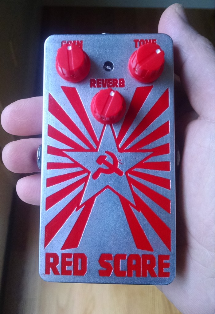
It has Gain, a single tone control, and reverb level control. The reverb room size is set by a resistive divider(R21 , R22) and can also be made adjustable. It utilizes a TPA3116D2 class D amplifier IC which can be configured for mono or stereo output.
Click Here for Large Schematic Image:
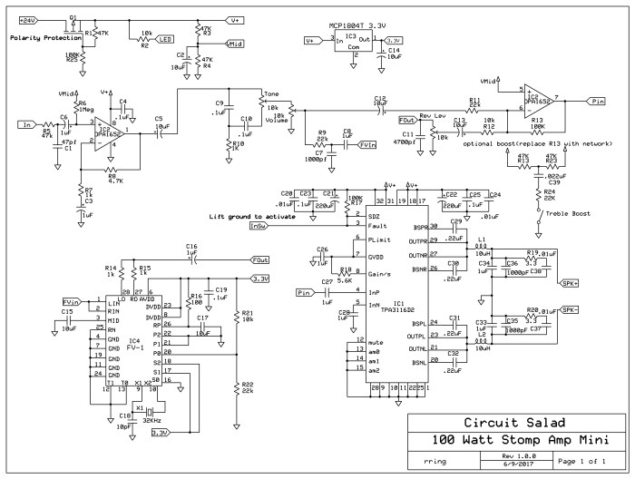
The amplifier sounds delightful. The class D topology provides greater than 90% efficiency. This eliminates the need for substantial heat sinking. The only penalty is that for guitar applications, pushing the amplifier to distortion does not sound so great. I use an overdrive pedal so I don’t care about this.
Update: I added a LED clipping circuit to make sure the input into the class D final amplifier is level limited(clips/distorts) before the final amplifier starts distorting
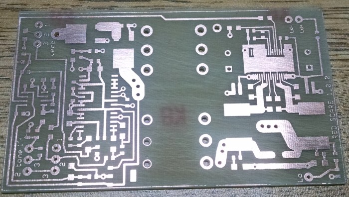 Home brew laser printer resist circuit board
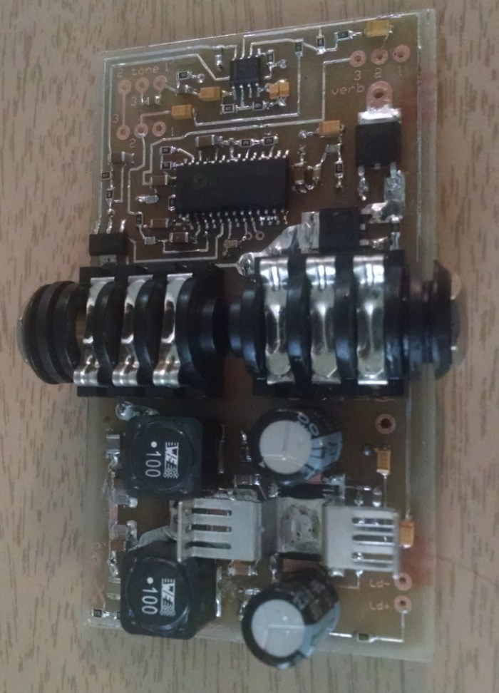
Completed Circuit Board
Link To CAD FILES: https://www.adrive.com/public/QpRQMX/RED%20SCARE.zip
The single tone control is surprisingly versatile. It alters the level and center of a MID scoop. You can get really FAT all the way to bright twang all with one control. The circuit can easily be modified to employ a more sophisticated tone stack if desired. The amplifier requires a 12-24V power supply with at least 4 amp sourcing capability. You can purchase a small lightweight switch-mode supply from Amazon for less than $20.00 that will work nicely. It is ridiculously small, lightweight, loud as hell, and sounds superb through a couple of 10″s or a single 12″ cabinet.
Quick Demo of built in Blue LED clipper limiter added to original prototype(you can see the LEDs flash as the input is clipped)
