
My call sign is W4KIA … I am on 40 meter CW a lot these days! Would love to get some help testing my antennas.
Month: October 2015
Efficient Half Size Dipole for 40 meters
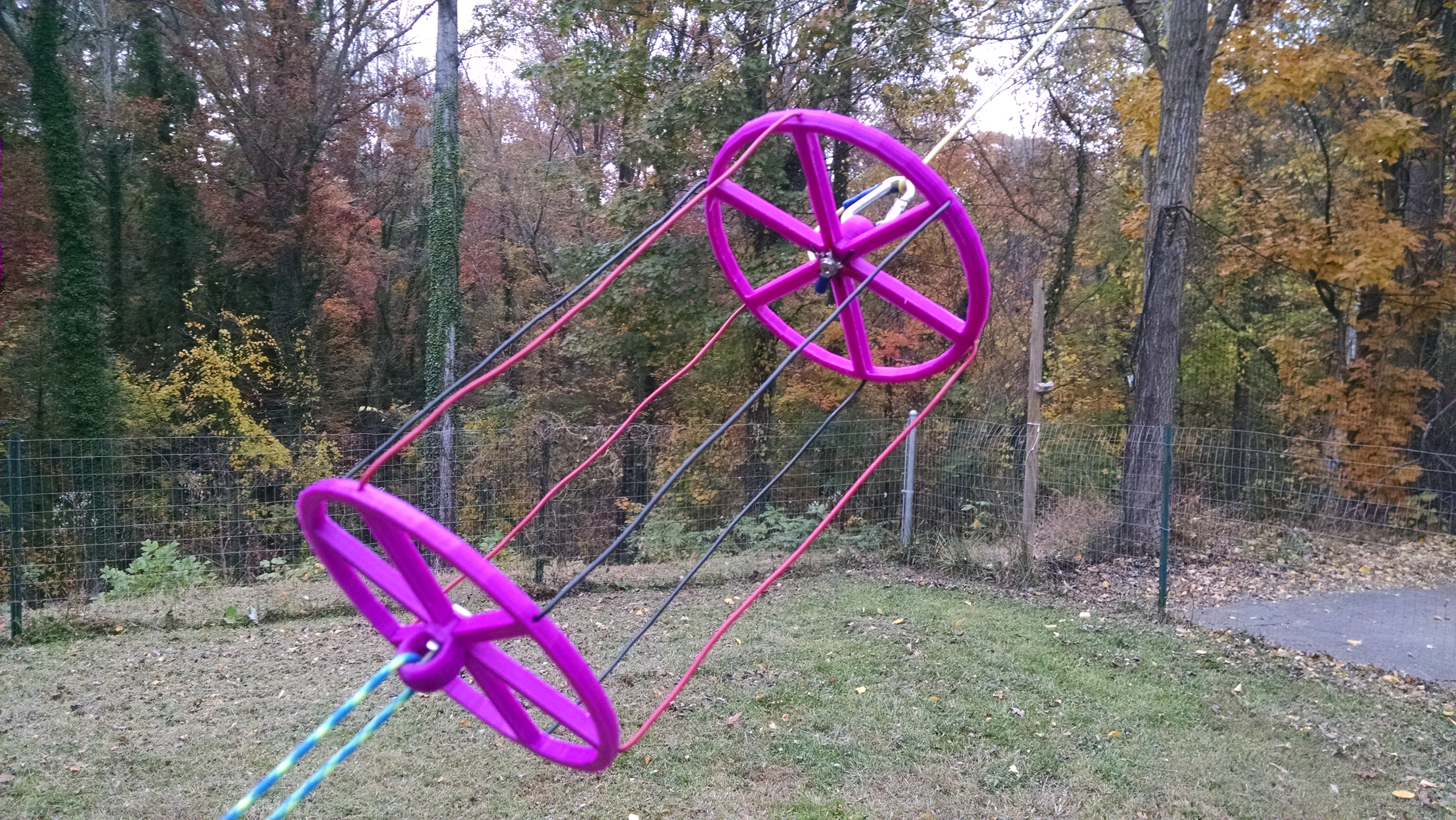
In my continuing saga of antenna experiments, I have designed a 30 (a little less than 1/2 normal size) foot long 40 meter dipole that is a solid performer. The goal was to make it short enough that it would work well in portable applications as a vertical or sloper hung from a tree. It is center fed with one continuous loading coil tapped at the center two turns to a SO-239 type jack for coax. A balun is not necessary because of the tapped connection to the loading coil. Along with the loading coil, there are two cylindrical capacitive hats which replace about six feet of wire each. The hats improve current distribution, bandwidth and efficiency, allowing for a smaller loading coil. The hats are lightweight and flatten out for very easy transport. The antenna uses carabiners and inline connectors to allow quick connect and disconnect for setup and removal.
Link To STL Files
https://www.adrive.com/public/F8Fsz4/Antenna%20Forms.zip
Antenna mounted as a sloper
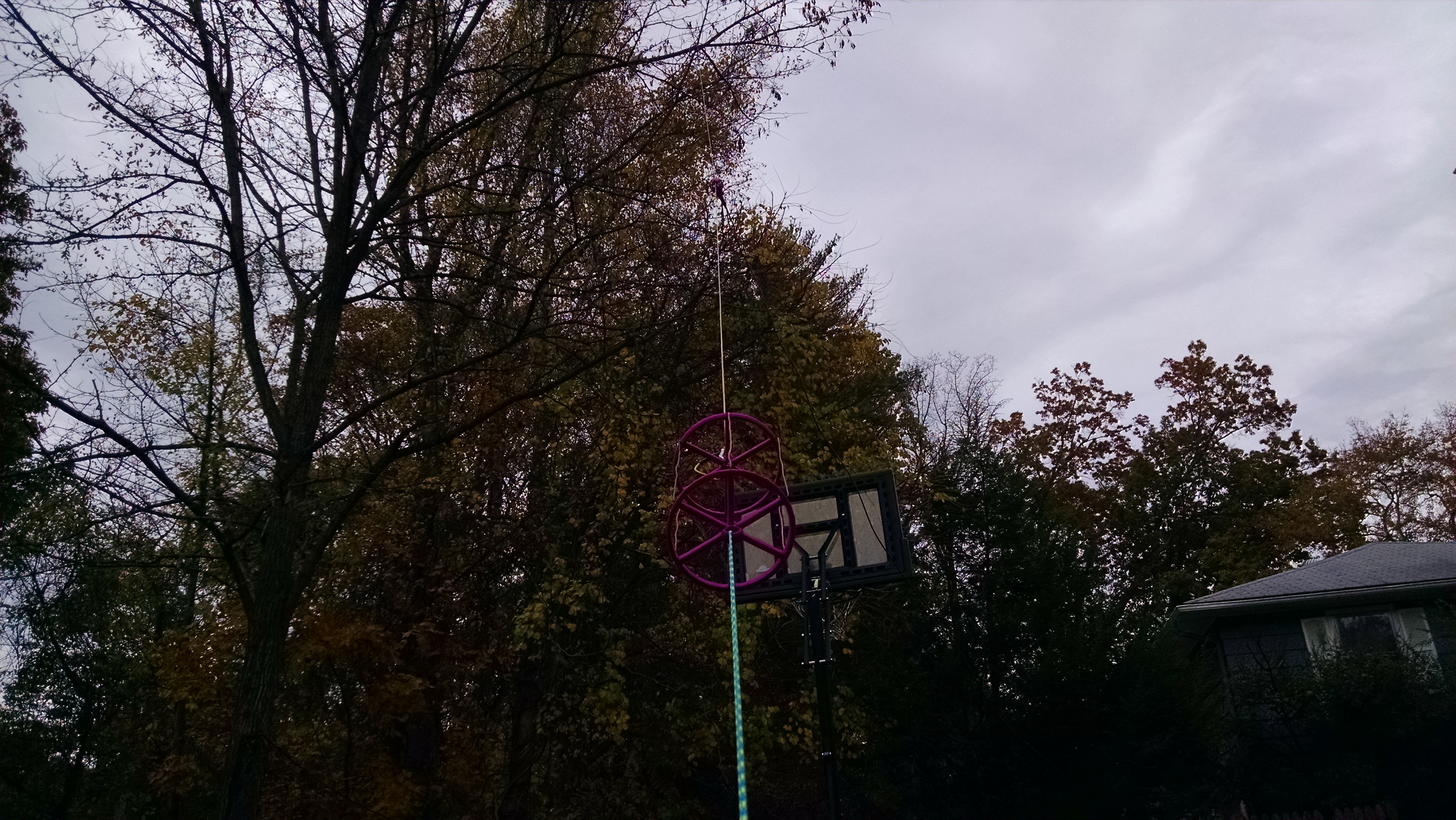
The Loading Coil and Hat frames were printed on my 3D printer using a low RF loss plastic material – High Impact Polystyrene(HIPS). Here is a link to the STL files which can be used to print these forms. An STL file is the standard format used by almost all 3D printers. If you do not have a 3D printer – there are online services available to 3D print the files as well as some print shops and office stores. Other plastics could be used such as ABS but use HIPS if you can. Because the antenna is relatively small you can mount it vertically or nearly vertical with the center relatively high above ground for better efficiency so besides being small, the antenna has some benefits with respect to ground losses and radiation angle (depending on how you mount it).
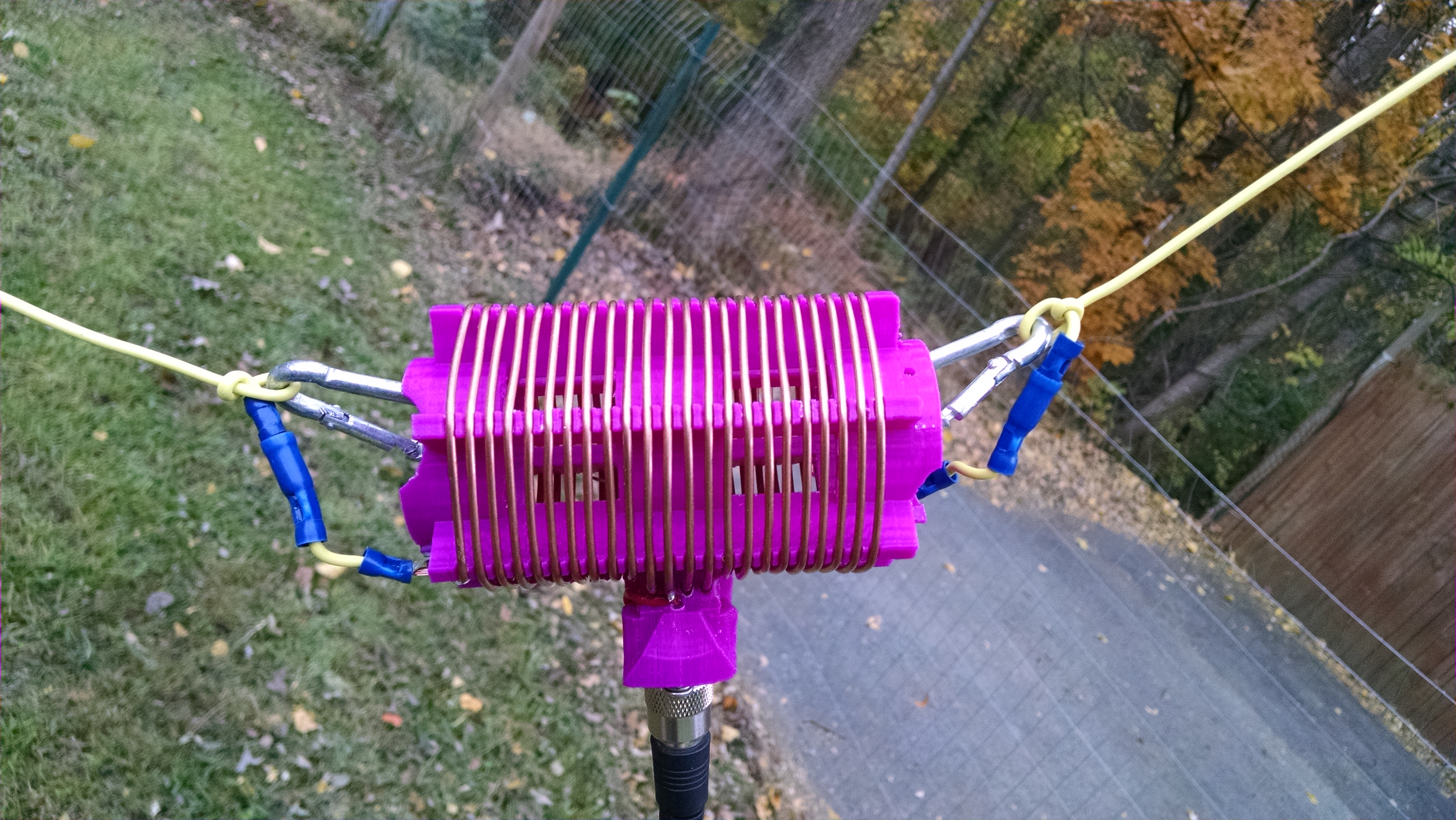
Loading Coil
Coil has 11 full turns(plus half a turn) to center from each side(3 inch diameter and 3/16ths turn spacing). It can use 12 gauge or smaller wire. The mounting holes can be tapped for 6/32 or 8/32 screws for the coil terminal and connector flange. Total coil inductance between 16-17 uH
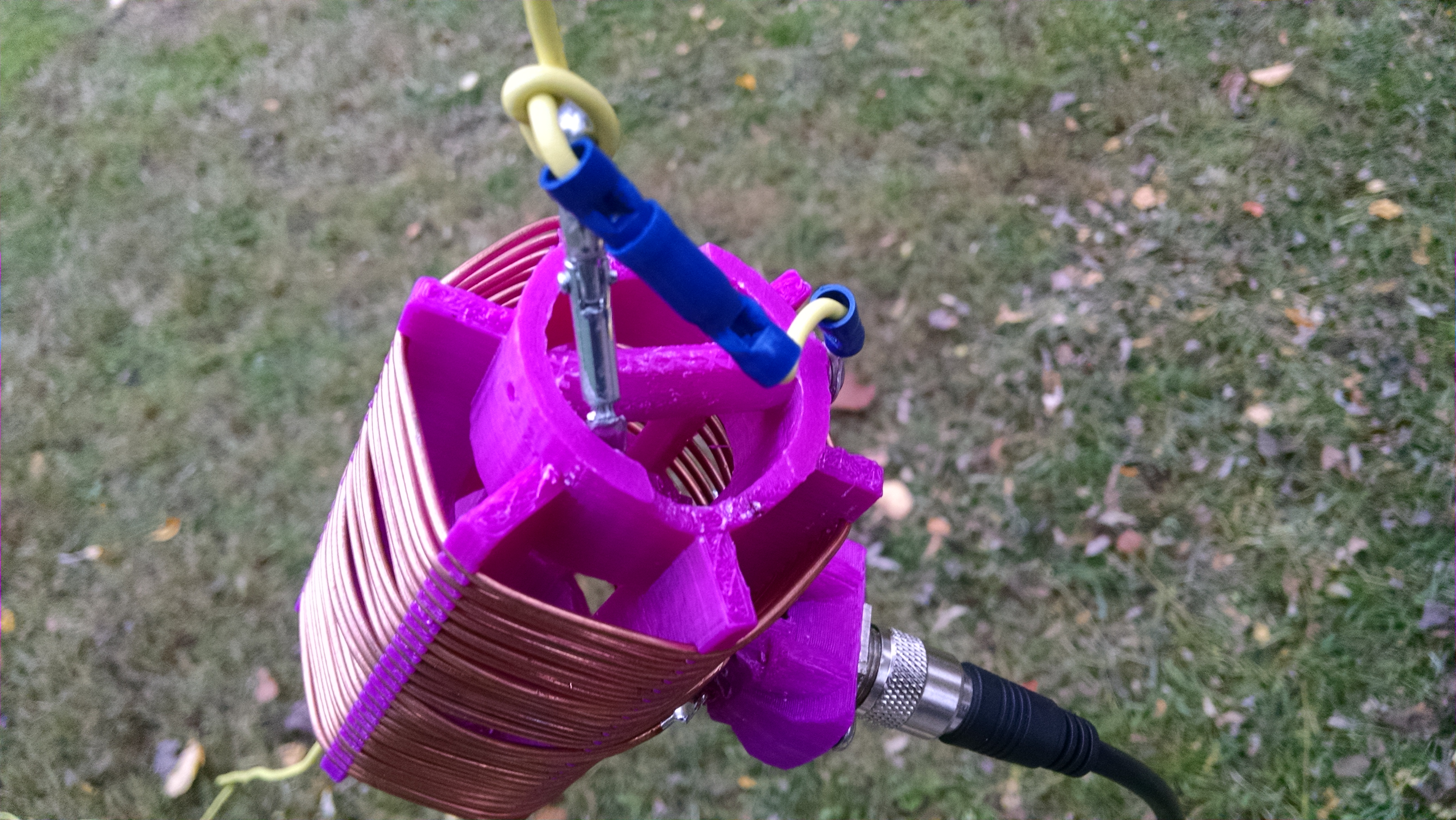
Capacitive Hat
The hats are 6 inches in diameter with the wire soldered together in the center and then pinned with a 8/32 screw and washer.
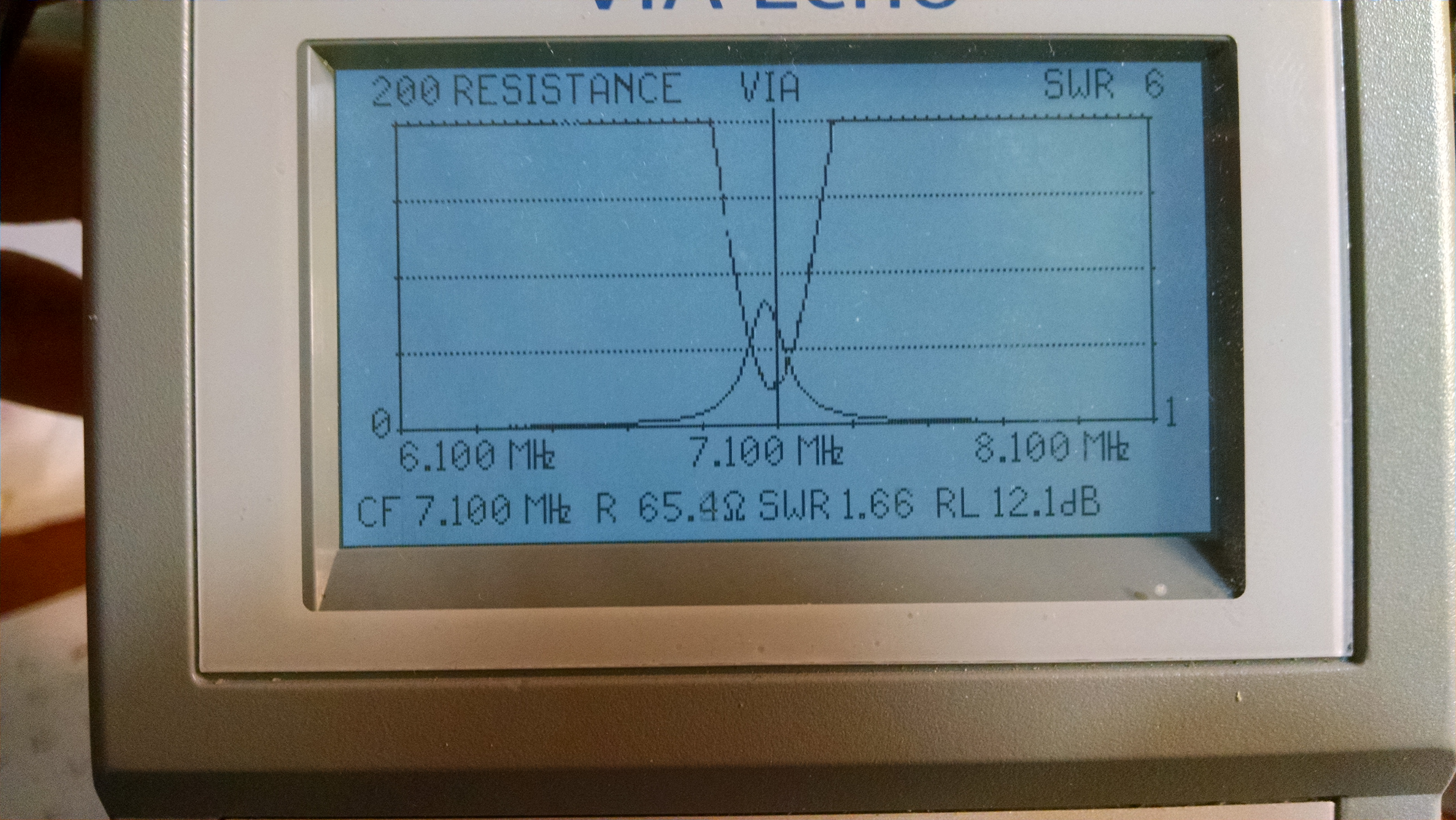
Antenna adjusted to resonance for 40 meter CW
Ultra Simple 8 pole Low Pass CW filter
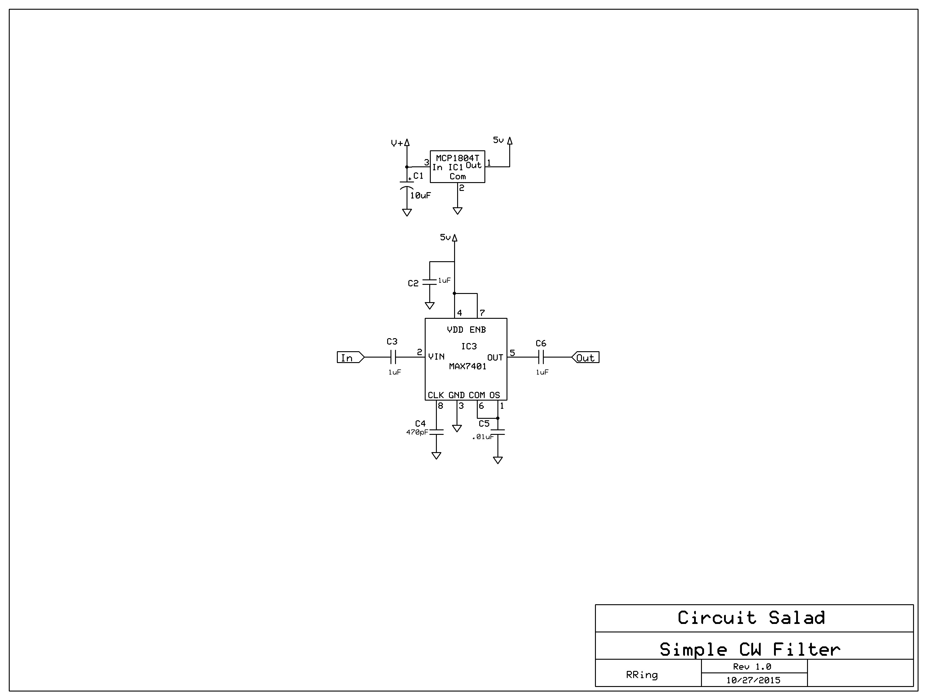
I wanted to add more audio filtering to my 40 meter CW transceiver https://circuitsalad.com/wp-content/uploads/2015/08/qrpxcvr2.jpg but didn’t want to put much effort into it, so I used a MAX7401, 8 pole switch cap filter IC. This IC requires just a few discretes and has an extremely low passband ripple and group delay, as it is a Bessel configuration. I have used this IC before in some of my guitar effects pedals. It has worked very well in my other designs. The knee of the filter is adjustable via a capacitor(C4). To integrate into my receiver, I simply connected the input and output of the filter across the input capacitor(C27 removed) connections to the final audio amp. It may be desirable to put a single RC low pass filter stage in series with the output of the switch cap filter to remove clk artifacts on the output.(clk is 100X greater than the roll off frequency). Performance is very good with clear tone and no ringing.
Below, I have a video demo of the XCVR utilizing the filter. This version of the XCVR is tuned via a POT connected to the microcontroller A2D converter instead of a rotary encoder. It also has a push button to shift in 5Khz increments. When the button is depressed for longer, the frequency in KHz is sounded in morse code. Only the KHz is sounded, so for 7.100 Mhz for example, only 100 is sounded in morse code. In the video you can also see my cool 3D printed Code Key. It uses rare earth magnets instead of a spring for key action. It’s a really delightful bug.
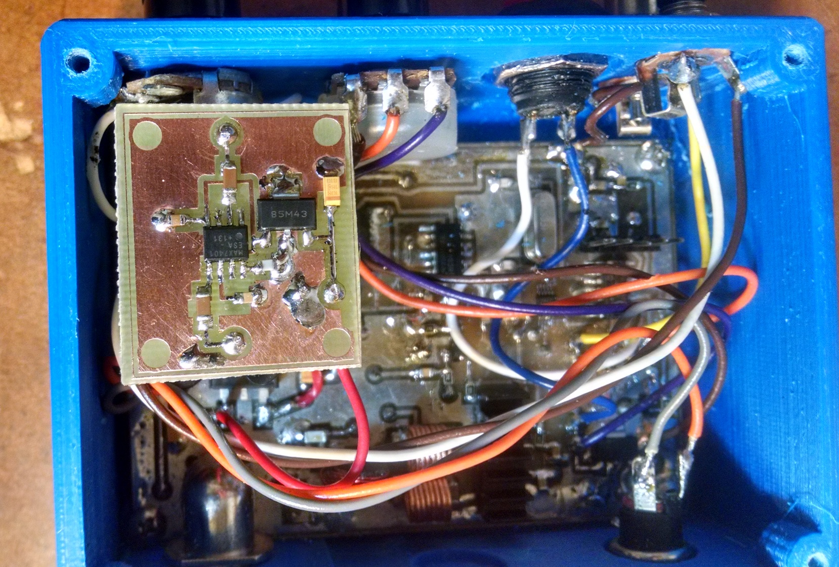
Picture of filter Daughter Board connected to XCVR
Filter Schematic
Video of XCVR using the Filter
Improved Power Toggle Latching Circuit
Awhile ago, I posted an example of a Power toggle circuit using a handful of components that I use all the time to allow a momentary switch to control Power On/Off function.
https://circuitsalad.com/2014/04/12/simple-momentary-switch-latching-circuit/
The circuit works well but can require a series diode with the output to prevent stored charge or magnetic energy from re-energizing the lating function such that it won’t turn off. The diode drop may be undesirable, so I modified the the circuit as show below.
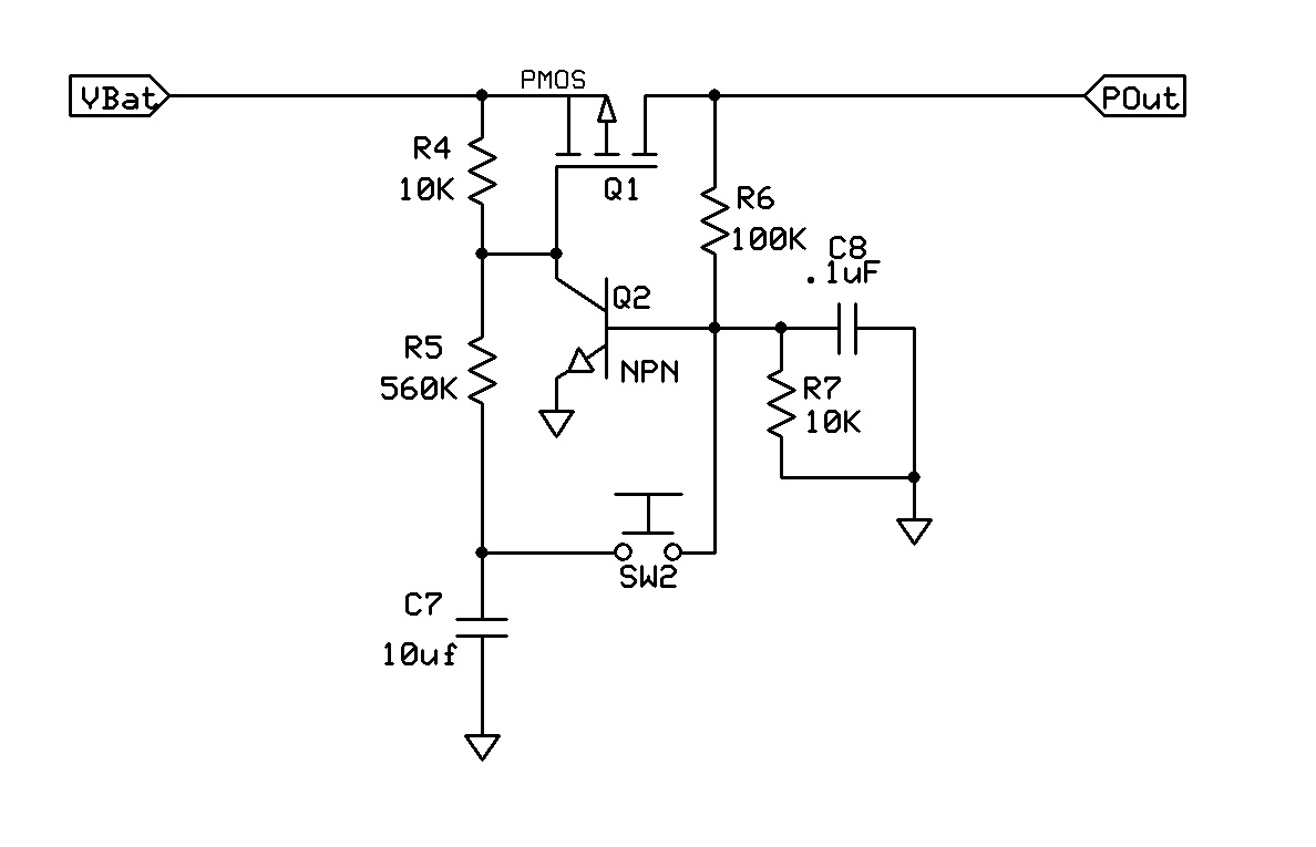
The addition of R7 and C8 eliminates this problem in every circuit I have tried and is sure-fire in reliability. Normally, C8 can be omitted, but I added for one application with very strong RF fields near by. As before, the circuit draws no current when off and can toggle within a second or so.
Of course you might ask why not just use a toggle switch? Well of course you can but you can get momentary switches cheaper, they can be much smaller and generally I find switch bats ( toggle levers) to be un- aesthetic and sometimes cumbersome. So now I usually do something like this.
More Spiral Experiments
I have come to the conclusion that my large(1 meter diameter) spiral loaded vertical is really an asymmetric dipole with the spiral being the other radiating element. For fun I made a much physically smaller spiral and attempted to use that.
New Small Spiral

I found it was extremely difficult to tune and narrow band as well. It did work but the receive level went down slightly so I have concluded it is not as efficient as the large spiral. Feedpoint impedance measurements were better matched(higher R) than the other spiral but this is surely IR loses in the dense coil.
My conclusion is a moderately sized spiral of a few turns(> 1/20 wavelength) is very effective as its area makes it a respectable radiator. If the spiral coil becomes small the approach doesn’t work so well. My large spiral is a solid performer and it is my opinion that it is preferable to a modest radial array.
