
This is my new qrp transceiver design. It uses the CS2000 clock generator circuit I use for a number of my receivers and a 74AC240 buffer as a push pull 1.5 watt final amplifier. The final unit uses my low power/low noise LCD display and is set to tune from 7.000 to 7.300 MHz.
https://circuitsalad.com/2014/07/31/very-low-power-3-digit-lcd-display-with-serial-control/
If one changes the the output networks (L matching and half wave low pass) and simply adjusts the software for tuning range, one can use any band desired. The inductors are air wound or made using scraps of ferrite taken from junk box inductors. Tuning is accomplished by means of a cheap mechanical rotary encoder. The Micro-controller provides the control signals for T/R switching, generates a sidetone and shifts the frequency 700Hz on TX. The transceiver supports full break-in keying. The input to the receiver is isolated during TX by means of a BSS123 mosfet used as a switch. A 2N7000 will work here as well. The receiver uses a leftover inverter stage as a RF amp. It works surprisingly well and also provides the bias for the switching mixer input. There is a 2nd order op amp low pass filter for CW. The coupling capacitor C30 is normally not needed for receive, but when the TX is keyed, there is DC imbalance on the output of the mixer switches – the differential audio amp will slam to the rails creating large key clicks on the side tone. C31 is required for stability when keying, without it, occasional parasitic oscillations can develop.
The circuit could be easily modified to use a VXO or VFO. One would simply have to modify the keying logic(connect key directly to TXRX signal and invert this signal for MUTE connection) One can use the remaining two 74HC04 inverters to generate a side tone and the the logic.
Update: Changed the band to 30m for fun. The only hardware changes were: L1 & L2 (.11 uH), C21 (800pF), L3 (.6uH), C22 & C23 (270pF). The 74AC240 works beautifully at 10 MHz – outputting the same 1.5 watts and even running a few percent more efficient. I must have nailed the matching network values.
Schematic(minor edit for key clicks 8/18/2015)

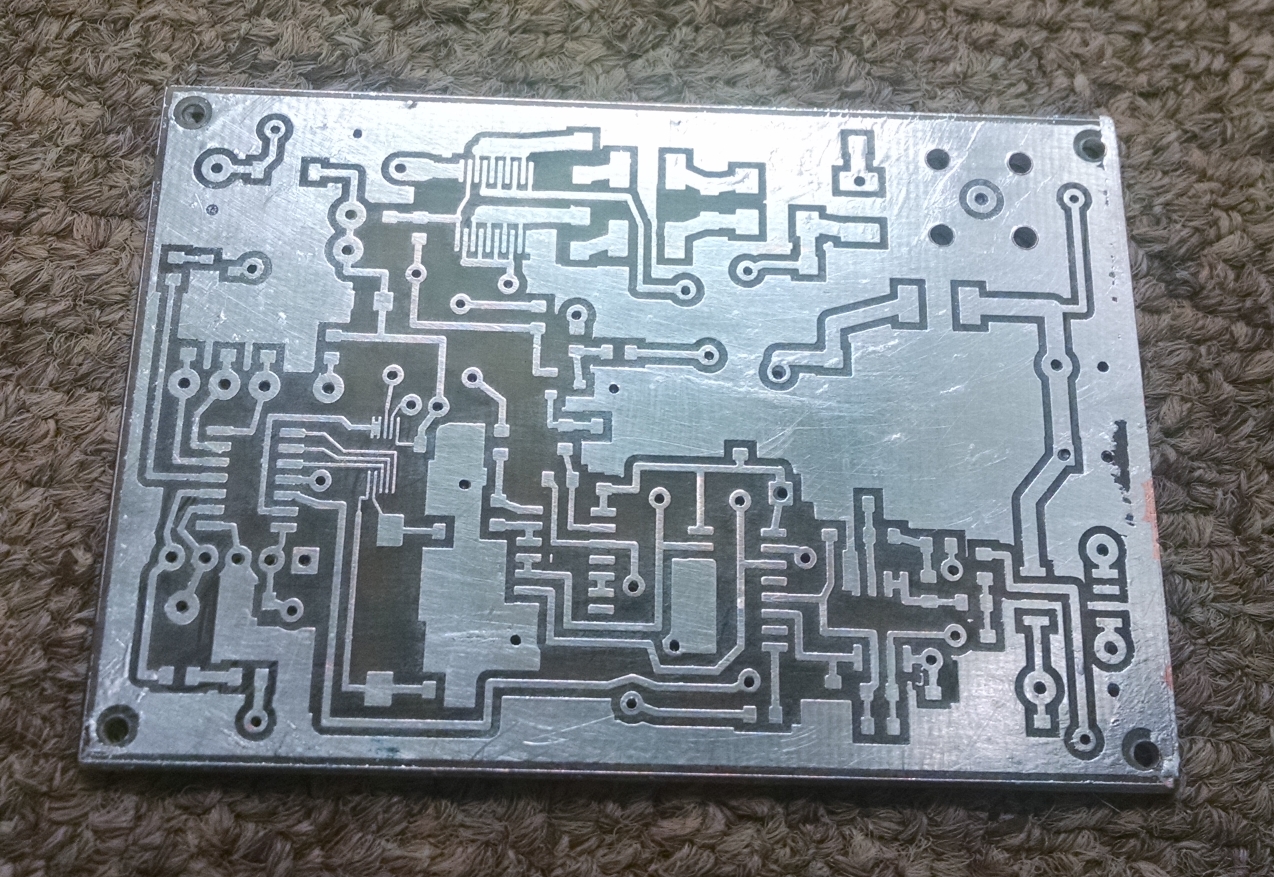
Unpopulated Home Brew board
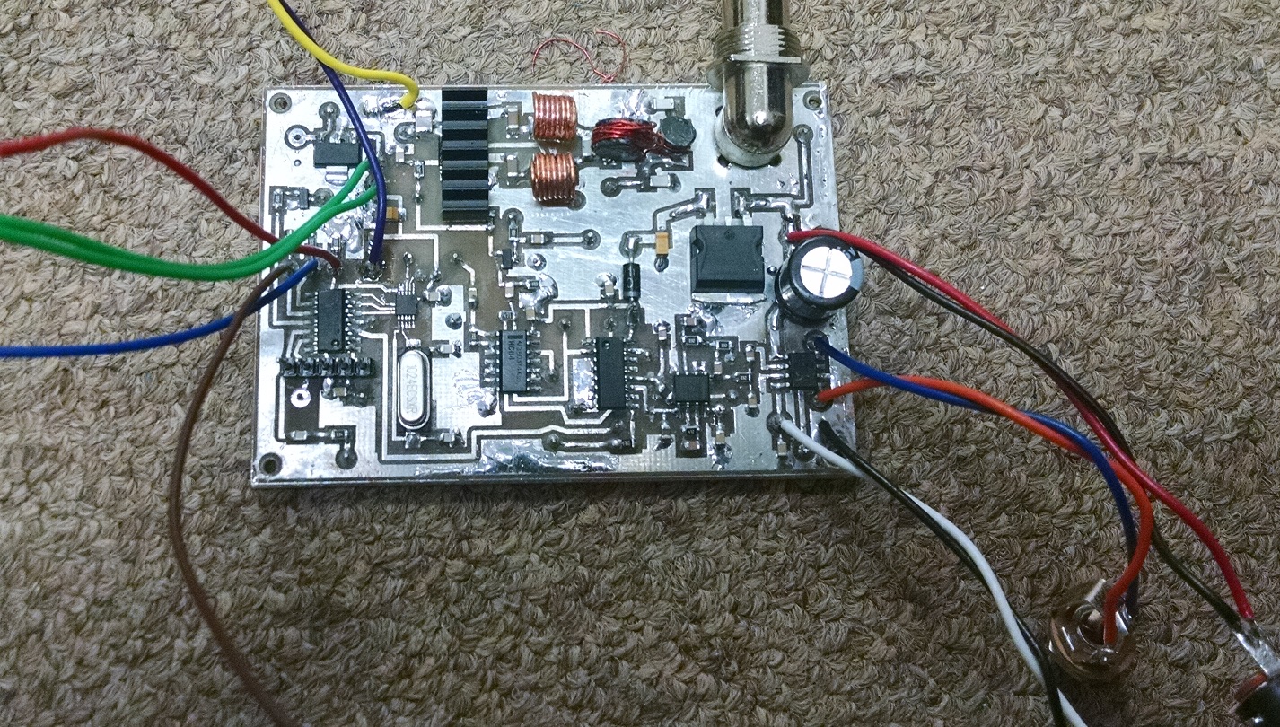
Populated board
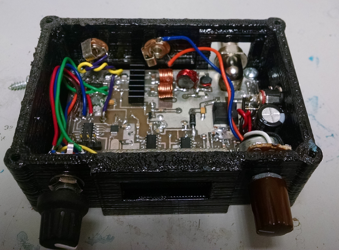
XCVR in Home Brew 3D printed Case

Video Demo

I noticed you used a 10.24MHz crystal with this implementation of the CS2000 chip.
Q: Did you encounter gaps in the tuning range when using that device and that crystal?
The datasheet implies the CS2000 will tune from 6 – 75 MHz regardless of crystal (Well, within reason anyway) but when I tested the chip, each crystal I tried gave different results, with gaps across that range. It may be that I’m simply not calculating the values required for the registers correctly, or I’m misreading the datasheet. (i.e. I’m still not sure what they mean about “12.20 format” and 12 bits of MSB and 20 LSB bits of fractional data) I calculate the required register values in my spreadsheet, load them and they (mostly) work, except when they seem to fall into a some sort of harmonically-related gap in the tuning range.
I am not exactly sure what your are describing.. let me clarify my use of the chip first. You can use any crystal you like. The chip generates some periodic sideband “birdies” (not many), but I chose crystals based on what I had around and making sure I had no spurious signals in band as well. I have used 8 Mhz, 22Mhz, 10.240…etc. You can obtain resolution of about 1Hz. As the crystal frequency gets above 16Mhz, you have to set a register to divide the reference back down. I use the high resolution mode and have no discontinuities (big skips?) at all in tuning from around 2.5Mhz to Max.
Here is my initialization of the part: (SpiCommand – writes the two bytes shown in hex to the CS2000)
SpiCommand(0x05,0x09); //freeze output until all writes completed
SpiCommand(0x02,0x00); //first config reg (all 0’s)
SpiCommand(0x03,0xC1); //ratio 8 selected, data enb1 set , R-mod 1to1
SpiCommand(0x16,0x10); //config to use OSC 16…0x08 !!!!!!!!!!!!!!!!!!!!!!!
SpiCommand(0x17,0x10); // PLL output when unlocked
SpiCommand(0x04,0x00); // Lock sel=00 (matches ratio select) so FracNsrc must be 0 also
SpiCommand(0x1E,0x00); //freeze output until all writes completed
SpiCommand(0x05,0x01); //freeze output until all writes completed
How I change Frequency after initialization:
In My code, I create a calculation constant, which is (crystal freq divided by 8) then all of that divided by 2^20. The value below is adjusted slightly for crystal tolerance(calculated value is 1.2207)
const float CalcConst = 1.22143; //(10.240 MHZ CrystalVal / 8 )/1048576 ->1048576 = 2^20
then I simply divide Frequency desired by CalcConst. So 7125000 Hz/CalcConst = 5833327
this result is loaded into FreqCalcVal(shown below) and written to the part
void SetFreq(unsigned long FreqCalcVal){
SpiCommand(0x06,((char *)&FreqCalcVal)[3]); //Freq higest byte
SpiCommand(0x07,((char *)&FreqCalcVal)[2]); //Freq higher byte
SpiCommand(0x08,((char *)&FreqCalcVal)[1]); //Freq high byte
SpiCommand(0x09,((char *)&FreqCalcVal)[0]); //Freq Low Byte
}
If doing a quadrature detector obviously your frequency needs to be 4X your desired receiving frequency
Does this help?
Yes, I follow exactly the same process….well, almost. I initialise the cs2k using exactly the same configuration, and then I calculate the value to load to registers 6 – 9. I do this by taking the four bytes stored in the uP for the decimal frequency (i.e. 7000000 Hz is stored as 00 6A CF C0) and calculating (C0 * j)+(CF*k)+(6A*m)+(00*n) where j, k, m and n are the constants for 1 Hz, 256Hz, 65535Hz and 2^24 Hz respectively for the crystal being used. This sounds crazy at first glance, but it’s faster to do four integer multiplies and three additions than a 32 bit divide. (I get the same result as your calculation method in any case…at least in my Excel sheet. Hmmm…)
But the resulting tuning range is non-contiguous. For example, a 10MHz crystal results in outputs between 2-4.5, 4.9-8.5, 9.7-17, 20-34, 39-68 and 78-130 (Yes, they do go up that high. In fact, I’ve had the chips running as high as 160MHz) and nothing in the gaps. If I use a 13.5MHz crystal, then I get 2.2-2.9, 4.4-5.7, 6.8-11.5, 17.6-23, 35-46, 70-92 and 141-166 (The chips tends to give up above about 165 MHz – They’re just not trying hard!!)
See the harmonic relationships in there? Hmmm, if you are getting a contiguous range regardless of crystal, then I’ll have to look at my calculation method again and double-check the values going to the cs2k. I’ve checked the I2C bus I’m using and that is working just fine so it’s not the data transfer. I’ve checked out a couple of chips and both do the same thing (using the same software)
I might have an interesting overflow problem going on in the software rendition of my algorithm.
Thanks for the help!
Hey I forgot to ask you. Did you do anything with the FV-1 yet? You mentioned in that thread that you had ordered some. Also after reading your detailed post – I am a little confused…so you are saying if you enter a value corresponding to a freq of 8.9MHz what happens? Does it just not change or go to the incorrect Frequency…not sure how you can put in a valid number and then it skips it?
Yes the divide is brutal! but was easier for me to calculate values on my calculator to check..etc(somewhat intuitive) also my runtime loop can be slow and work well- so didn’t worry about it much. Overflow sounds like a possibility. Very cool with the 160 MHz- haven’t tried that high but could be useful! Settling time is quick and tuning in very fine resolution is smooth…It must be a math issue?
FV-1: This took me a little time to organise. Did I mention I live in a place which lacks a postal service? I have to sync stuff like this with trips to civilisation. Well, I now have the parts (FV-1s, crystals, EEPROM) and just last week, I sent the PCB design away to the fab house in the depths of China (which has an excellent and nearly free postal service, go figure). Long story short – I’ll collect my PCBs in London over Xmas. Santa is coming…
OK, so back to the CS2k….Boy, this is odd. Basically, depending on the xtal fitted, I get different results. I just send the (correct) data to those registers and if the chip likes the data, it will output a signal. If it does not, it refuses to output anything. As I tune with my rotary encoder, I get bands of output and bands of no output.
Example #2 (13.5MHz case was #1): With a 12MHz xtal, I get 2.18-2.55, 4.4-5.11, 8.8-10.2, 18-20.2, 35.4-40.4, 70.1-81.25, and 141-166. BTW, the output (when it’s there) tends to fall over about 90MHz, but it’s still useful.
I’ve checked my maths again, and the software as far as possible, and it all seems to pass. So, in an idle moment last night, I tried some other crystals. I kept the “Div by 1” set in the chip throughout. I got wider bands of output (and fewer gaps) with a 16.93MHz xtal. Not supposed to work, but it does. And checking the reference output on pin 4 confirmed it was oscillating at 16.93 MHz.
I tried a 17.5 MHz xtal. Even better results, fewer gaps. Huh. So I went for broke and fitted the only higher xtal I had in my box of bits, a 24MHz xtal. And, golly, I got complete 2 – 166 MHz output without any gaps!!
So now I’m really scratching my head.
I’d ask Cirrus what’s going on, but they don’t ever seem to bother answering questions on their website. Heaven help us if I was doing this stuff for real in a production environment with 100,000 parts backing up on the line…
I also share the I2C bus with a tiny I2C 16×2 LCD (Same results with or without that in place, by the way), and the response time of the whole thing is really nice. I have a bunch of tuning rates all working fine, but just not with the xtals as specified by Cirrus.
I cannot figure this one out. Bother. (Sorry for the long post)
It must be some config bit is wrong somewhere or something. I just don’t see any of these problems? I will look over the data sheet. I remember early on with this chip some goofy things happening when I didn’t quite have it configured correctly. There must be an explanation?
I am excited to see what you can do with the FV-1. I was hoping for more enthusiasm about using the part for dsp radio but know one else seems to interested. Oh well. I plan to revisit it with a more refined receiver design.
Yes, I agree. The config is the most likely source. I’ve gone over these carefully, more times than I care to think about. However, I’ll have another look over the weekend. That’ll give me a couple of days away from the problem in the hope I see something then that I don’t see now.
That FV-1 is amazing. It’s surprising others haven’t tried it, but sometimes it takes a little time (and example code) to get things going. I have a phasing rx partially built ready to test the FV-1 board. I had planned to use the CS2k as its VFO, but had to use an older AD9850-based design initially to test the RF front end while I was trying to sort these problems out.
Another month until I’m in London, and then a few weeks of holiday, before I can get the PCBs (which the Chinese production house tell me are already flying to London ahead of me) and then get back here to build up the FV-1 test board. I want to try out some adjustable CW filters too, just to see how they work in the FV-1.
Waiting for Santa to visit (with the PCBs) is such a trial…
At first I had had a crazy problem where I was using the part in the wrong mode….where instead of the reference as the source I was using the “dirty”clock input but that pin was floating. Amazingly it was occasionally pickup 60Hz hum and locked to it..it worked but was unstable! I realized I had to tie pins 4 and 5 together and put it the correct mode. As you found the part seems to work well beyond the range of frequency spec’d. It settles quickly as well. Those DDS chips use so much current and require so much filtering. I have built a couple but prefer the clock generator chip. I’m sure you will get it working. Keep me posted on your FV-1 experiments…all I ever did was cascaded first order IIR filters but you definitely can make then tunable which is on my list to try. I am also interested in your digital IQ balance tweaking for carrier null which described from another DSP effort and how that would be applied here.
Locking up to noise? That’s a sensitive input! I’ve tied pins 4 and 5 together and I have a test point on there to allow me to double check what reference the CS2k thinks it has. But…more head-scratching required from my end over that problem.
Yes, those AD9850 modules do suck current. Surprisingly noisy too. Harmonics from the 125MHz clock got into an adjacent GPS receiver module and killed 20dB or so of sensitivity. The CS2k is a welcome relief from both problems.
I’ve also got some SI5351 chips waiting for me in London as well. I suspect most of my future effort will be focussed on those devices. Although the current is higher than the CD2k (30mA vs 10mA), the difference is negligible for my applications. The big improvement is price. The original price of the AD9850 from Analog Devices was around $70, from memory. Those Chinese modules were about $5, the CS2k was around $4 or so (but with that excellent current improvement), but the latest price on the SI5351 is less than $1 in 10-off quantities. That’s pretty amazing.
And, for sure, I’ll let you know if and when I figure out this CS2k problem, and how I get on with the FV-1 chips. I’m looking forward to trying a version of the code used with the ancient TMS320C DSP chips back in the day and comparing results. Should be interesting…
Great… I looked at the SI chip but did not find it until I had put all the work into CS2000. The SI may be a better choice as there are some periodic artifacts that can show up with the CS2000. I’m just too lazy to start over without a good reason. Let me know if you find it to be meaningfully better in performance – which would motivate me to develop code for the part!