
I decided to try using IGBT’s in my optimized half bridge Tesla Coil driver circuit. The results were good but the IGBT’s did have more heating than the very low RDS on mosfets such as the IRFP4229. I was able to phase shift the drive feedback such that zero crossing switching was achieved, but the Collector to Emitter voltage of approximately 1 volt @ 10 amp current produces 10 watts of dissipation, whereas the IRFP4229 RDS of. 04 ohm yields only 4 watts of dissipation @ 10 amps. So for a low power coil the FET is a better performer. At much larger currents, the IR dissipation the Mosfet grows exponentially, so in DRSSTC designs the IGBT would be a better choice as its dissipation grows linearly. My test coil operates at nearly 400KHz. This is a very high frequency for IGBT’s. The main issue with IGBTs is that they are slow to turn off when driven to saturation(switching). I chose the STGW35HF60W 600V, 35 amp ultra fast IGBT for my experiments. It is optimized to minimize turn off delay and residual tail current. It worked well at this frequency but the price you pay is a higher Collector to Emitter saturation voltage than you get with slower IGBTs. So again this is a trade off. Over all these IGBTs work well in the circuit and while they do get warmer than the Mosfets, they do not overheat with the small heat sinks and switching losses are low. They seem tolerant of abuse and I have not blown any up yet!
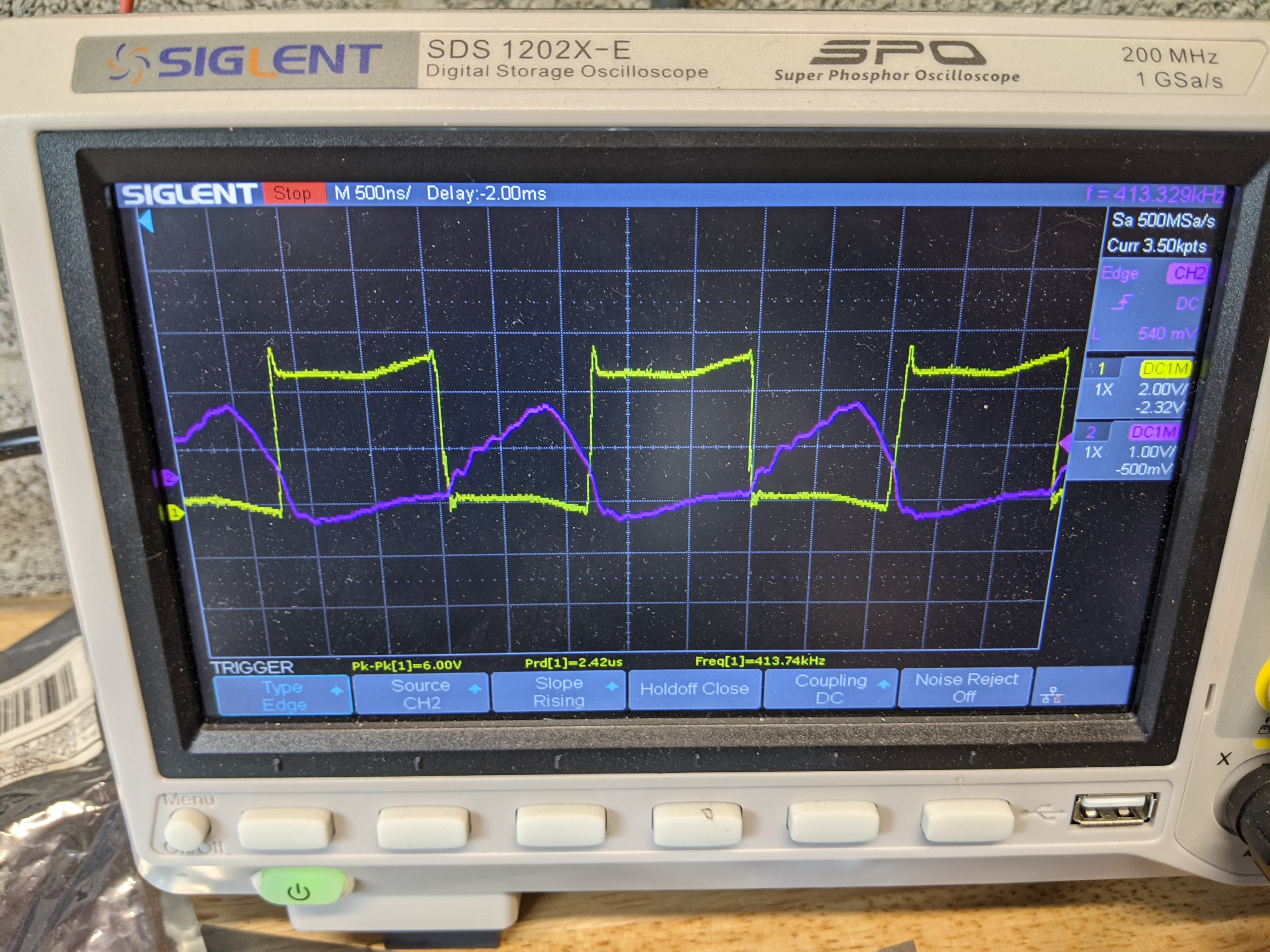
Optimized ZVS switching with IGBT’s
