
I have been doing some experiments with super simple switching mixers that will make it easy to build a Ring Modulator Pedal without the diodes or doubly balanced Gilbert Cell mixers. Still working on the basic circuit but it should be very easy to build. More to follow.
Month: May 2013
The Very Cool MRF49XA ISM band Transciever
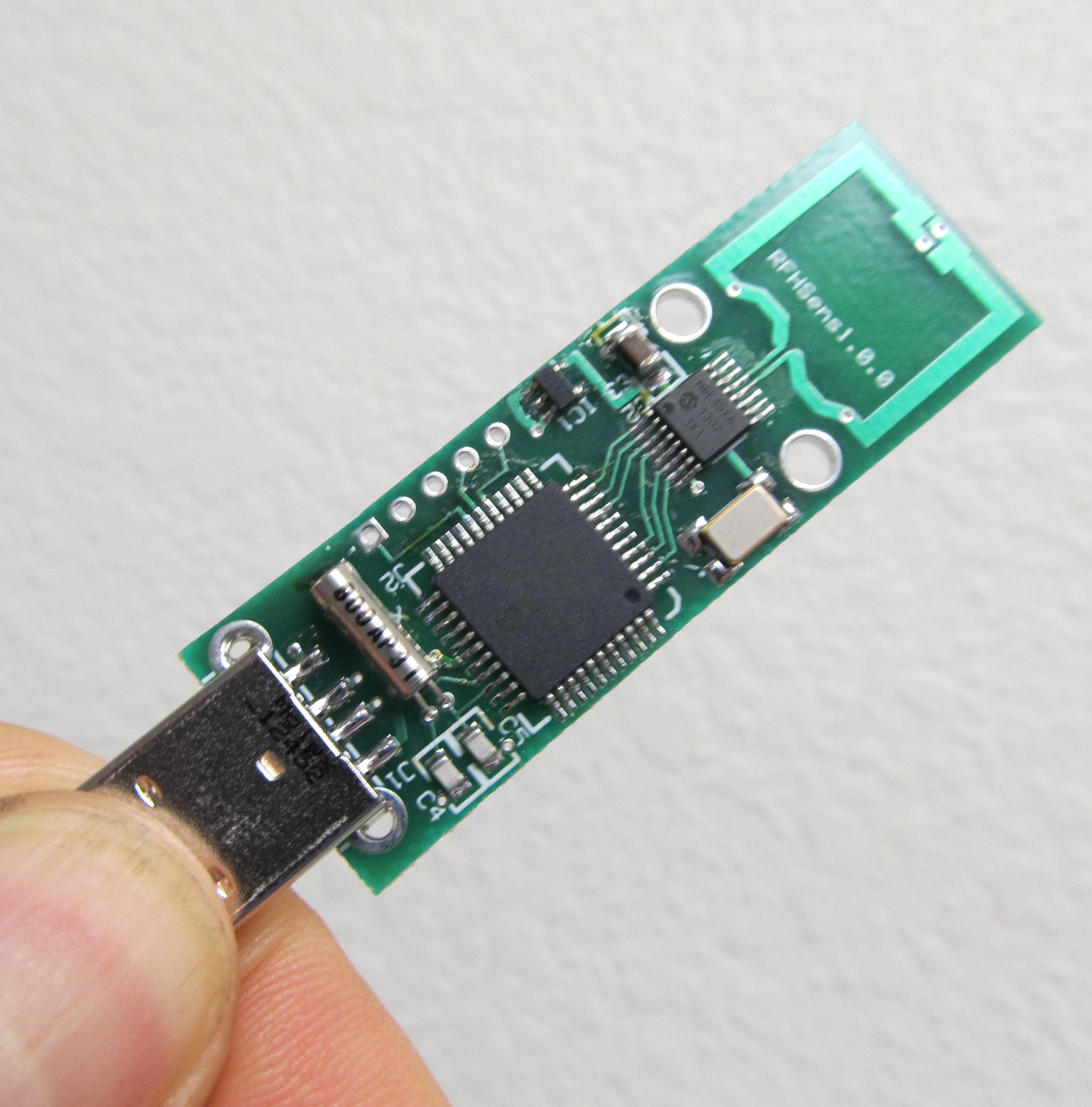
A few years ago, I remember seeing a highly integrated radio transceiver for 433 MHz and 915 MHz. It was produced by Integrated Associates, which then was bought by Silicon Labs. Recently, I found the same part sold by Microchip as the MRF49XA. It is a really cool part, requiring only a crystal and some decoupling caps, if you use the balanced loop antenna as I have in my design. If you use a standard 50 ohm antenna – you will need a few passive components to provide impedance matching and balanced to unbalanced conversion at the output. The radio uses a DC conversion topology and requires no IF filter circuits. It also provide antenna tuning, and internal TX/RX switching etc. Microchip has a very good data sheet which explains how to use the device.
In the picture below is a little USB transceiver I designed to demo the device. I will post a demonstration video showing a couple of these in operation. You can see from the picture, there are not many parts at all (there are two decoupling caps on the back)! The challenge was writing all the code to configure and operate the radio circuit and create the USB link. I created a generic HID USB device which requires no special drivers in windows. I ended up building a complete library of routines to operate the radio and configure its frequency, power, network ID, baud rate, etc…. The device works very well and with this antenna has a range of about 200 -300 feet. Much better performance can be had with a better antenna but this requires more board space and or the matching components discussed above.
more to follow…
Make your Transistor act like a triode
I have thought for some time that by adding shunt/shunt feedback to a bipolar transistor or mosfet (a JFET also but only AC coupled), that it would emulate a Triode tube with respect to the output I/V curve. So I decided to simulate it and check. These devices, when biased for normal operation, have a output response that becomes independent of the supply used. This is the same for a Pentode tube like a 6L6, EL84, etc, where the screen grid has a constant bias allowing the plate voltage to vary significantly without changing the current flow through the tube. By adding shunt/shunt feedback, which in this case is a feedback resistor from the collector to base of a Darlington device, the output I/V behavior becomes constrained by the biasing of the base and therefore affected by the changing voltage seen at the collector.
Shown below is a simple amplifier circuit, simulated in SPICE, using a Darlington but without the feedback. You can see from the I/V(current is the Y axis and voltage the X axis) curve that at a couple volts or so, the device is in the active region and as the voltage increases the current stay mostly the same. The current through the device becomes independent of the voltage across it – like a Pentode or saturated mosfet.
Now lets add the shunt/shunt feedback as shown below. You can see with the new circuit, that as the device is turning on, there is a small but highly non-linear region. This is because the supply voltage is below the point of actually biasing the device all the way on. As the supply voltage is increased, the device is biased on but the current through the device now is dependent on the supply voltage because as the supply voltage changes so does the base bias and therefore the current flow through the collector circuit. The alters the I/V behavior the device to act like a Triode where the output I/V behavior is much like a simple linear resistor.

I used the Darlington in the manner in my Battery Amp with excellent results.
Variation of Battrey Amp Schematic with Demos and new layout
I modified the circuit of the battery amp to put the volume control before the first stage like the original FET version of the amp (one of the first posts). It really doesn’t sound that different – It just allows you to have really high output input sources without overdriving the first stage. It is very easy to modify the original board layout to do this. On the final stage, I also modify some values because of the altered gain distribution.
Here Is The New Schematic showing what needs to be modified:
https://circuitsalad.com/wp-content/uploads/2013/05/portaamp3b.gif
if you compare to the last version – its not that different.
Here is jazz demo with some compression from my simple opto-compressor and the amp set with a little mid size room reverb and mid way settings on the Bass, Treble and Presence. The guitar is a cheap beater electric that cost me $150.00. It is always fun to see if you can good sound out of crappy guitars!
https://circuitsalad.com/wp-content/uploads/2013/05/night-and-day-with-comp.mp3
Note: In the this schematic and layout below, I changed one of the select lines for the FV-1 to use a different reverb algorithm – not a big deal – I just like it a little more than the original.
Here is a new board layout that requires no modification and reflects the new schematic exactly:
http://www.fileswap.com/dl/v1TrMfdse/
Here is the schematic as shown above but without any references to modification:
https://circuitsalad.com/wp-content/uploads/2013/05/portaamp3bfinal.gif
