PWM Phaser using PIC DDS LFO and 74HC4066 analog switches as synthetic resistors

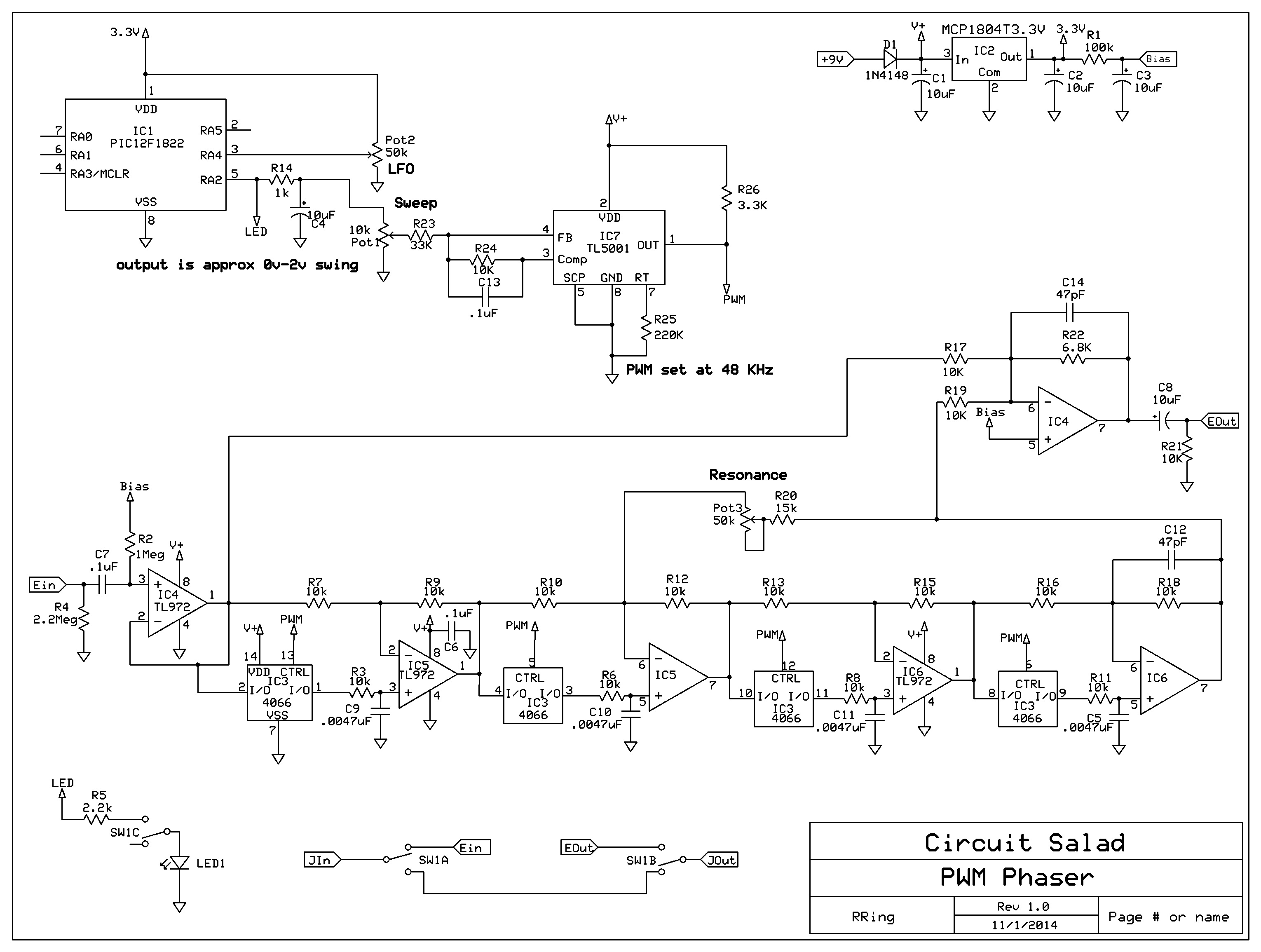
I finally got this thing working well. I am using a TL5001 PWM chip  at 48 Khz to pulse width modulate analog switches in series with 10k resistors. The average resistance seen by the all pass filter circuits is proportional to the on time of the switches. For example is the switches are only on half the time, the average resistance is 20k instead of 10k. The advantages of this approach are that there are no critical adjustments, good dynamic range, and extremely linear resistance change in proportion to control voltage. The current draw is 25mA or so…not great but better than the 50mA I started with. The LFO is a DDS sine generator using a PIC micro controller. I will include a link to the code and a working hex file. I only use a sine wave output but the code can easily be modified to support numerous wave forms and frequency ranges. The  code for this project has been modified in two ways from the DDS code described in my other blog entries. I lowered the internal clock frequency to 8 MHz from 32Mhz(saves current) and reduced the output swing of the sine wave so it did not drive the PWM chip beyond 90% duty cycle.  Originally I just use the PWM directly from the PIC with no filtering but found this created noise artifacts, so I filter the output and drive a PWM chip. Typically, phaser circuits like this use high pass filter structures at the positive input, I chose to use low pass to help eliminate the switching noise from being introduced into the output. This worked well and eliminated the need for extensive filtering. The output is very clean

One thing that is very cool about this design is that it has variable sweep range instead of depth control. So the frequency range of sweep of the phasing notches can be adjusted starting at 100Hz or so all the way up to 5KHz.
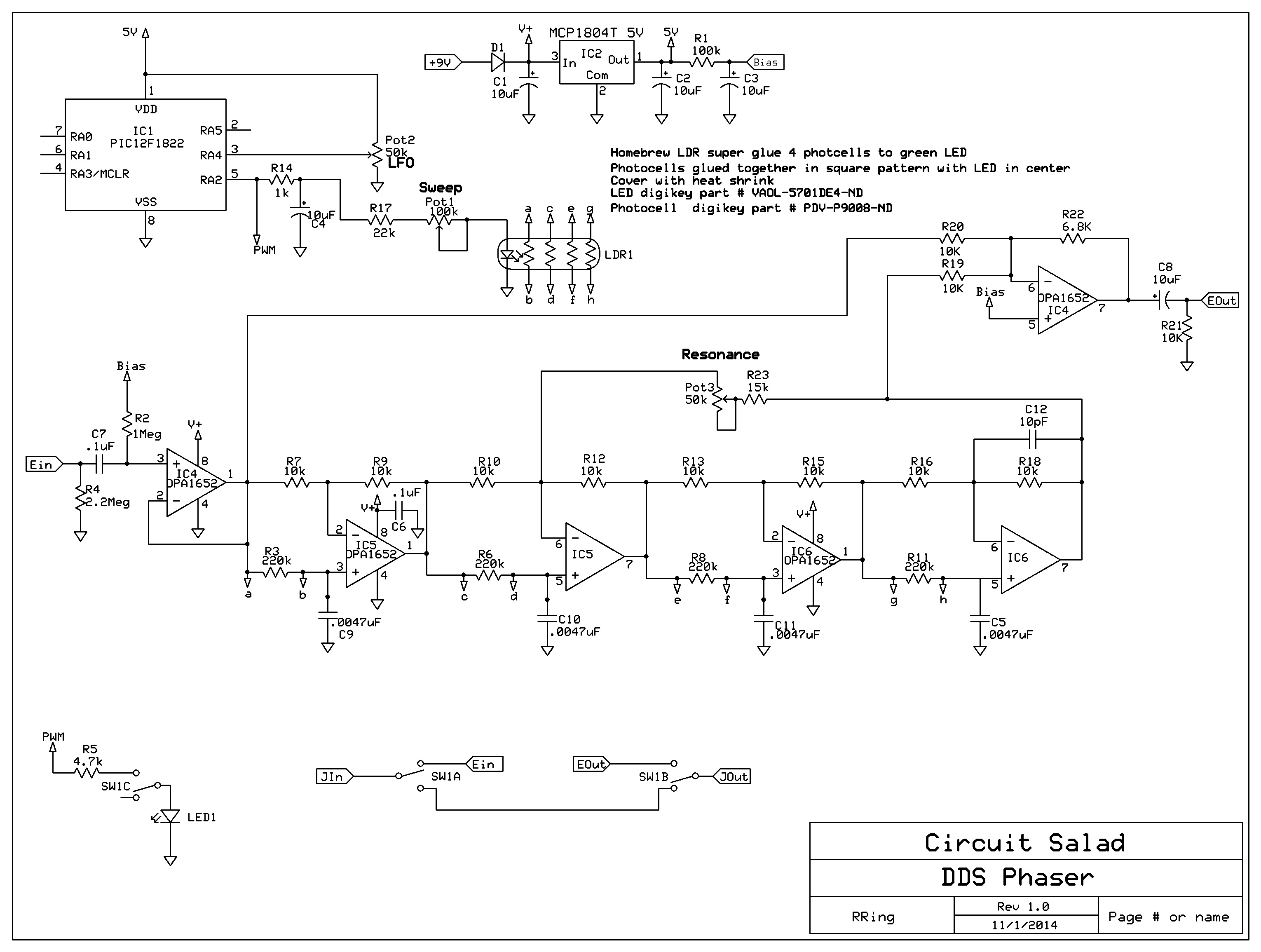
Schematic:

pwm phaser


Demo

Link to code: https://www.adrive.com/public/mWSkFb/PWM%20phaser.zip

Another Quick Demo of my “No Tuned Circuit” Direct Conversion Radio

This is a video of me listening to radio Cairo in my basement while working on other projects. The slight drift from zero beat can be heard at the end. This is from the transmitter drifting… not the receiver. I know this because I have looked with a frequency counter and the receiver stability is within a fraction of a Hz. This is really the only drawback of this radio- that you have to zero beat AM. Still it works pretty well as is.

My next step is to go back to quadrature output again and build a simple DSP demodulator out of popcorn 12bit ADC’s and a PIC micro. This way I can listen to AM without zero beating the carrier. This is done by generating two outputs 90 deg out phase, squaring them, summing them and then taking the square root. This gives you the magnitude of the envelope of the carrier or the AM modulation.

New phaser with Homebrew 1×4 Vactrol and DDS LFO

I decided that I  should build a Phaser using my PIC DDS LFO. I designed a PWM version using CD4066 analog switches but this had issues. It just drew to much current and had some noise artifacts. I got it working but it became more complicated  than I liked. However, the design was easily modified to use a homemade vactrol. The vactrol uses four photcells glued together to make a square and then the LED is glued right in the center. The whole thing is then covered in a piece of heat shrink, electric tape or whatever.  Performance is excellent and the circuit is simple. Of course the DDS can be replaced by some other conventional LFO circuit. The main issue is operating the LDR’s in a good range to get even and adjustable notch sweep. With this design, the sweep is adjustable and you can even eliminate one notch by pushing its position sub audio. The sweep controls the level of illumination of the LDR’s and thereby adjusting the total range of phase shift. The LFO uses my PIC DDS circuit and generates a Sine wave envelope. The code can easily be changed to generate other wave forms. I am going to include a link to the a zip file containing all of my source code. This was all compiled using MikroC. The program is small enough to compile in the freeware version of MikroC or you can just use my compiled hex file.

More detail on the PIC DDS is available on this blog in earlier post.

Link to source code and  hex file:  http://www.filedropper.com/ldrphaserdds

Completed Phaser:

brainwash

Schematic:

LDR phaser

Etched Circuit Board:

etched phaser brd

Completed Board:

phaser board

Homebrew Vactrol:

quad vactrol