
link to the design:
https://circuitsalad.com/2014/05/06/a-simple-ldr-envelope-filter-that-is-just-delightful-to-use/
I designed a low pass type envelope filter using a Fliege filter topology . The result was a really easy to build filter that provides1st order low pass ..all the way up to 2nd order low pass with extreme bandpass peaked low pass(high Q, resonance…etc). I really like this pedal.

Demo Sound Clips:
Short attack, max intensity:
Mid Attack, low intensity:
Long attack, high intensity:
This filter topology has some nice features, such as:
Fixed stable gain of two in the pass band, regardless of Q
Highly adjustable Q
Uses only two op amps
Low parts count in general
Well suited for single supply operation( in my case I just direct coupled the input to a half supply biased input stage)
It also has a couple of drawbacks:
It requires three LDR’s unlike the Mutron for example which only uses two
I could not get a TL072 to work well in the circuit. I needed to use a higher bandwidth, rail to rail type op amp, but there are plenty of amps that work well.
The OP Amps I tried were the OP213(works fine but expensive), OPA1652, and the TS922. These are all low noise, high bandwidth devices. The TL072 broke into oscillation and distorted. Maybe someone else can get it to work? I don’t have time to figure out the problem but I assume there is some sort of undesired phase shift making an oscillator out of the thing.
The LDRs can be commercial units but I just built some from scratch – they were easy and cheap to make. I used flat faced green LED’s and small CDS photo-resistors. I super-glued them together and then just cover with heat shrink to make them light tight. It took me about ten minutes.

LED glued to photocell:
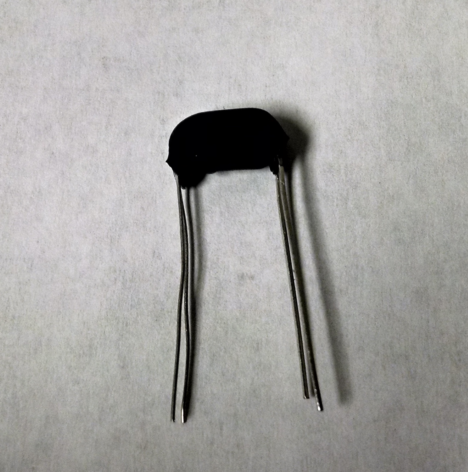
Final device:
The parts I used are: LED digikey part # VAOL-5701DE4-ND and photocell digikey part # PDV-P9008-ND
Circuit description:
Pretty simple – A emitter follower buffers the input and provides 1/2 supply bias for the the filter op amps. The Filter uses two LDRs for the filter sweep and one more for the intensity or Q of the filter. When LDR3 is .707 the vaulue of the other LDR’s (1 and 2), you get an ideal 2nd order low pass characteristic. When LDR3 is higher you get bandpass peaking and this can be quite extreme. As the filter sweeps, the ratio between the LDRs must be the same, that is why you need the third one and not just a variable resistor.
The LDRs are driven by a current mode amplifier and a simple diode peak detector. I used a LM358 for this but the the OP213, OPA1652 and the TS922 used in the filter section will also work. The design provides a sensitivity control, intensity(resonance) control and an attack control. The attack control really makes it easy to dial in the sweet spot of the filter and get very snappy or very slow plodding whah whah effects.
Circuit Schematic:

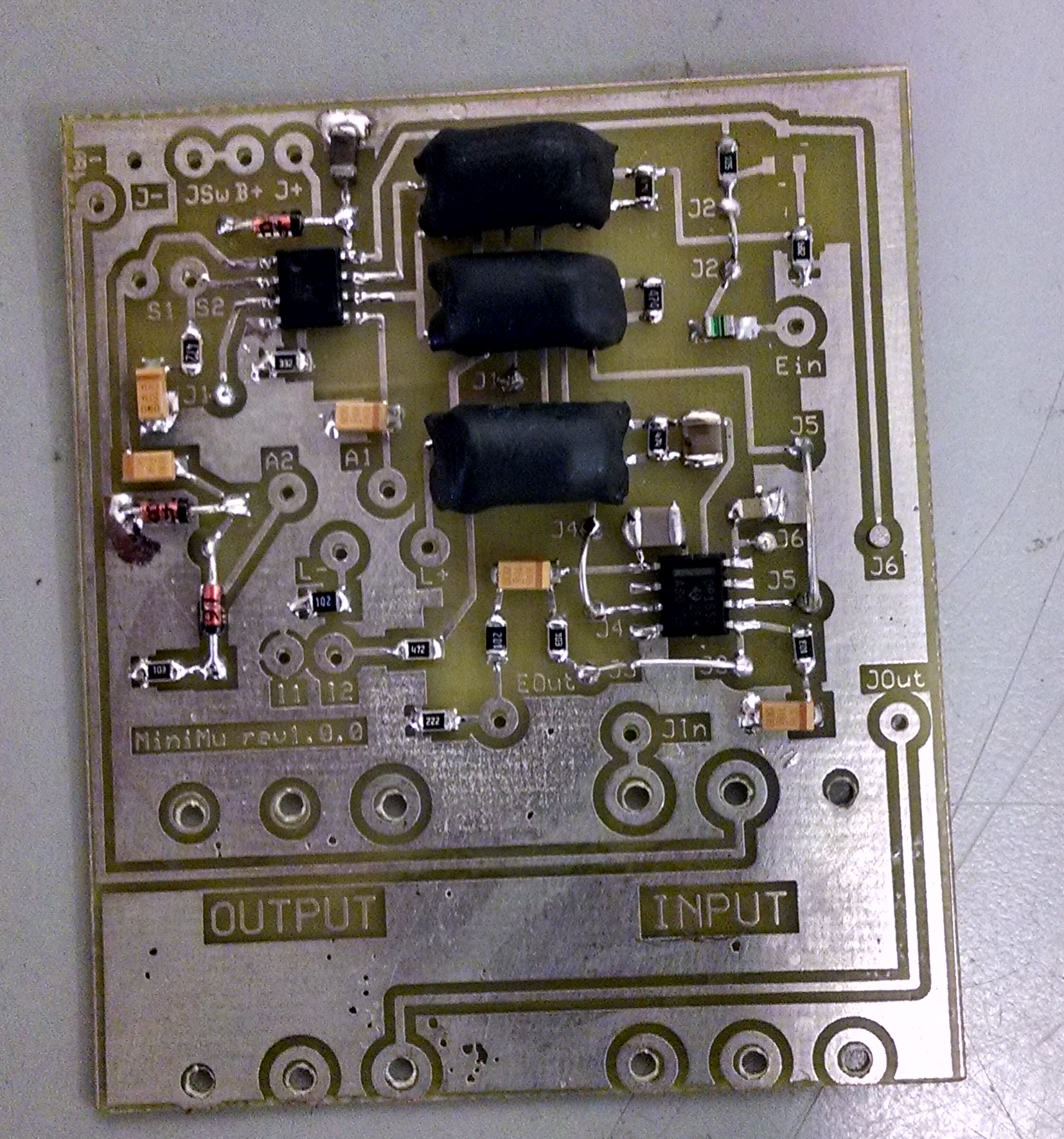
Populated surface mount circuit board:
Link to silkscreen:
Click to access minimussilkscreen.pdf
Link to Top layer surface mount layout:
