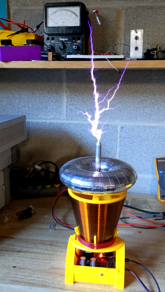
The McTesla is small 1000 watt half bridge Tesla coil with 3D printed forms for the terminal, secondary and the enclosure. The plastic used was PETG, which has low dielectric loss. The primary is 4 turns of 16 gauge automotive hookup wire(thick jacket) separated from the secondary about 1/8″ by means of 3D printed spacers. The power is provided directly from the mains through a half wave rectifier. The actual foot print is for a bridge rectifier but with a jumper wire you can fit the selected single diode on the board. Either will work fine. I get a little more crackle out of the half wave version so I just left it in place.
The secondary is 5″ tall and 3′ in diameter at the bottom and 5″ in diameter at the top. This alters the distribution of inductance of the coil and all but requires you have a substantial top load to suppress corona on the upper part of the winding. I get larger arcs with the conical secondary than an equivalent cylindrical secondary…maybe an inch or so more spark. I need to analyze why this is the case in more detail. The math shows a drum coil with equal diameter and height produces optimal Q. However, I think I am getting better primary coupling and impedance match allowing more energy couple to the secondary. It is wound with 700 turns of 33 gauge wire and resonates at 350 kHz. I tried 27 gauge wire and it worked fine. It resonated at 600kHz and streamer length was a couple inches less. Anything between 33-28 gauge will work well.
I have tried all sorts of different finishes for the secondary, including: polyurethane, and two part epoxy, ultimately, I ended up using 3 coats of spray shellac. It dries very quickly and you can apply 3 coats within a couple of hours. I found that when the coil is properly tuned and primary coupling is correct, a heavy insulative finish is not required.
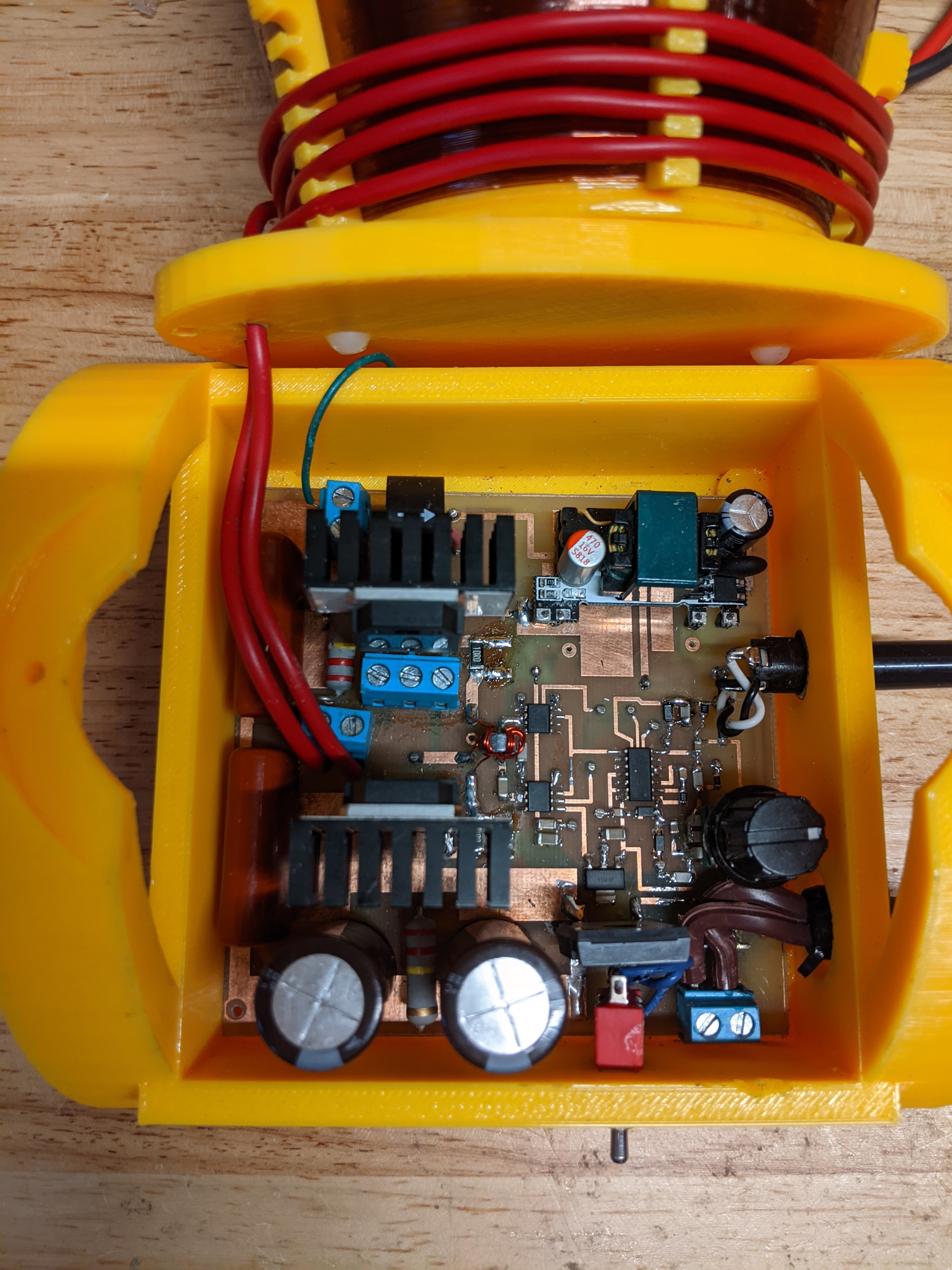
The half bridge architecture I used for this is described in more detail in a previous blog post: https://wordpress.com/post/circuitsalad.com/1875 . The main feature is the inclusion of a simple passive adjustable phase shift network in the feedback path. This allow one to minimize switching losses by minimizing current and voltage overlap in the mosfets. The end result is the FETS are less stressed and need less heat sinking. In this design, I have made some minor changes from the previous circuit. I am now using the IXTQ52N30P 300V@52 amp mosfet instead of the IRFP4229. The first IRFP4229’s I got worked great but then the next two I ordered failed quickly. As well, they seem scarce and hard to source so I thought it best to try another. The IXQ52N30P is near indestructible and I have yet to blow one. I simplified the modulation input circuit and decided to remove the diodes I was using across the gate drives. The diodes were in place to ensure the mosfets were not both conducting at the same time but I found when properly tuned, this not needed. I also used terminal blocks for the mosfet connections for easy experimental swapping or replacement . You can see this on the picture of the circuit board below. The driver board uses a 200:1 current sensing transformer for magnetic feedback to generate self excitation. This feedback signal is then phase shifted with a two stages of RC low pass filtering. One stage is fixed and the other adjustable. The adjustment range is from about 1 MHz to 200 kHz and is very forgiving. Optimal adjustment can be achieved by use of an oscilloscope, but simply tuning for the largest spark and then reducing the resistance of the POT slightly works well too.
Here is a link to all the tech data and files: https://www.adrive.com/public/5RrD3r/McTesla%20Tech%20data.zip
It includes native expresspcb cad files, schematics, gerbers, 3D print files and software development files
If anyone is interested in building this device everything you need is provided in the download. I am sure there will be questions which I am happy to answer. The interrupter is not required and can be replaced with a momentary switch or any other modulated switch closure. Some of the component choices are non-critical; such as 1N5819 diodes. The UCC27322 can be used instead of the UCC27321. The gate drive transformer can be any small 73 type ferrite material balun core or toroid. Other current sensing transformers will work but the CS1200L is a good choice and available. Certain IGBT’s will work well as well as other mosfets. You may need more heat sinking depending on the device selected. The AC to DC 12V module is a cheapo pcb module from Amazon. https://www.amazon.com/dp/B07SJRX9R6?psc=1&ref=ppx_yo2_dt_b_product_details

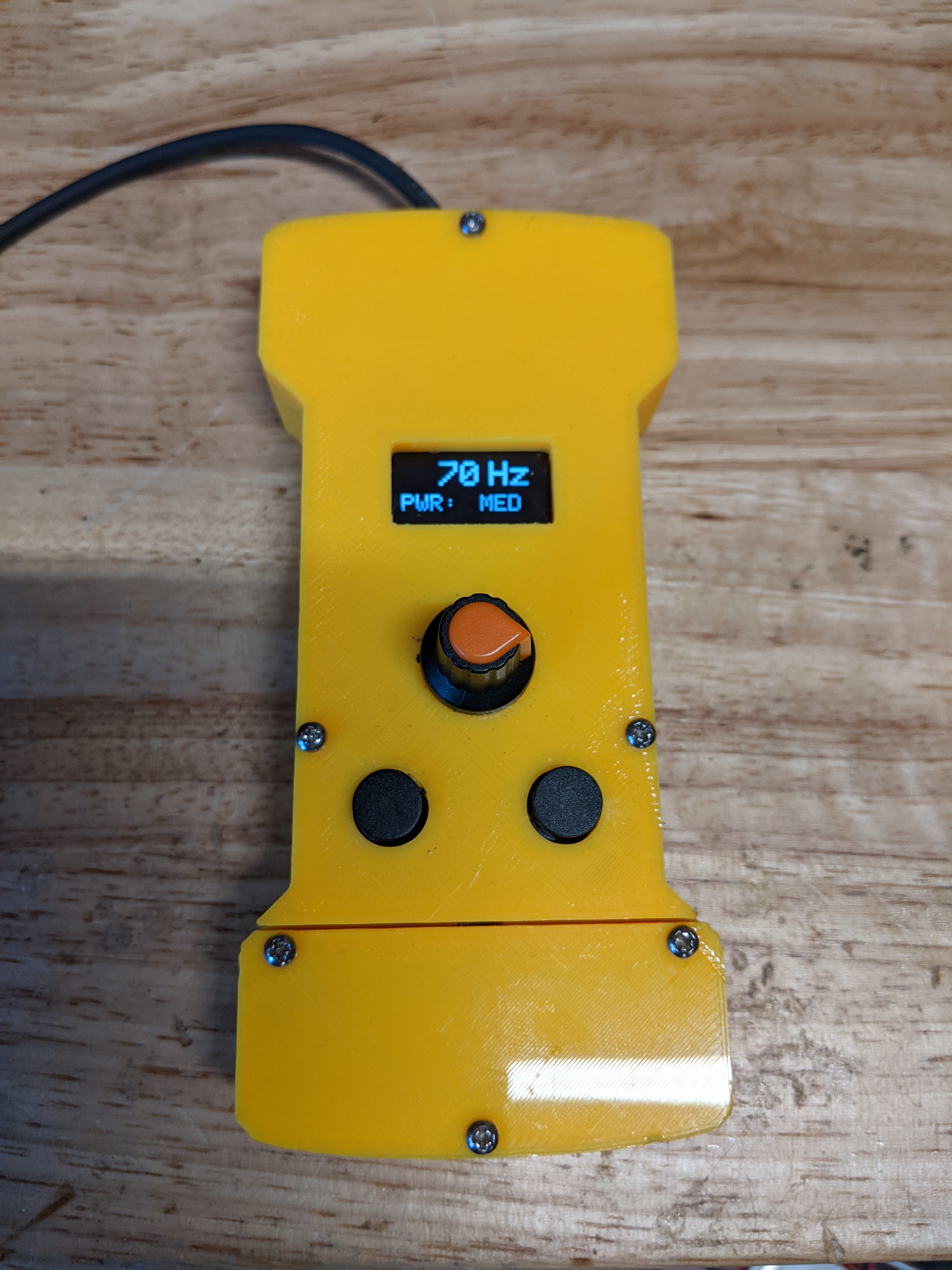
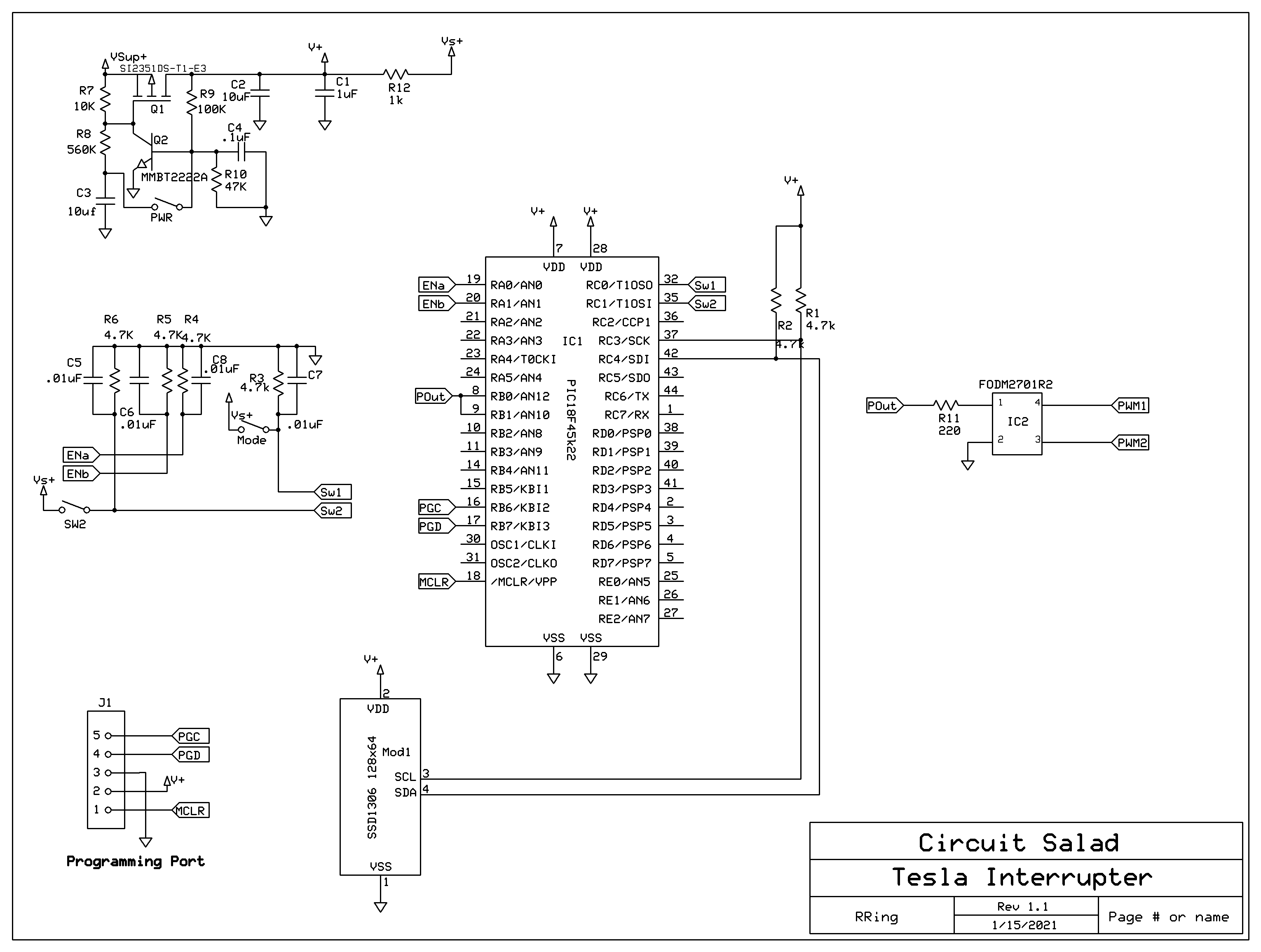
The Interrupter circuit is based on a PIC microcontroller and uses a simple opto- isolator as a transistor switching output. The OLED display used is a common 128×64 SSD1306 type. Ironically, I didn’t use the PWM output on the chip and created my own in software….but you easily could. I have it setup to provide 4 different duty cycles up to 50% , which can be adjusted by means of the two buttons. A rotary encoder sets frequency from 1hz -220Hz. I have driven the coil with 20Khz and it works. The momentary switch on the encoder is used to turn on and off the device. The software was written in C with the MikroC pro compiler. Next, I will make a PWM modulator to play music!