
I took my 20 foot short 40 meter vertical and tried using a spiral tuned counterpoise instead of my 24 radials. The counterpoise is off the ground only about 5 feet so the antenna is still ground mounted. Before I describe the details of the design. I want to discuss performance. With ground mounted radials I was getting a little over 50% efficiency. This is derived from a predicted feedpoint impedance of 18 ohms, but measured impedance being 31 ohms(13 ohms of losses). Using the spiral counterpoise; the feedpoint impedance is about 21 ohms – which implies > 80% efficiency. The only draw back is the tuning is a critical with about 6 inches difference between un-usable and perfectly aligned. As a practical approach, I made the spiral a little long and then I adjusted my coax ground connection point- to tune the antenna. I have made no effort to match perfectly to 50 ohms and the SWR is 2:1- over about 100 KHz. Tuning need only be adjusted when using a different portion of the band or moving physical position is some significant manner(placing lower to the ground for example). Regardless, there will only be about 6-8 inches of adjustment ever needed to tune the antenna. A L network or broadband transformer may be desired, to match to 50 ohms. Adjusting the feed point up the antenna a little, should also work to get a better match. The counterpoise appears to work very well and I can recommend it as an alternative to radials. I am assuming the radiation pattern is the same but I have not evaluated this. Of course making contacts is not a good measure of antenna performance but I have made contacts using the antenna in this manner -so it certainly works. Based on my measurements, it has less loss using the spiral counterpoise vs ground radials.
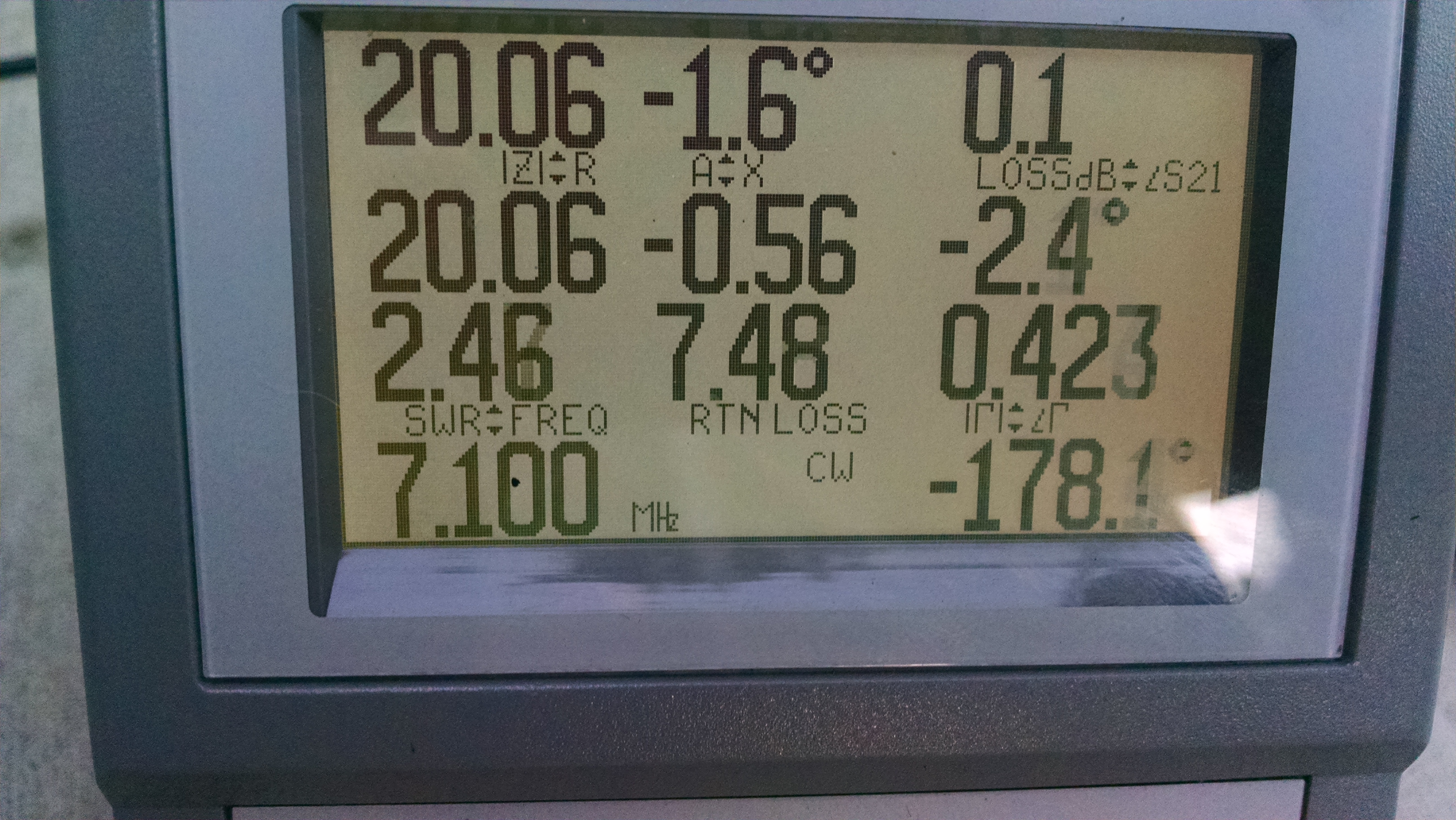
Short Vertical Tuned Antenna Impedance with Spiral counterpoise
20 ohm Z with almost 0 reactance (-1.6 deg)
Tuning the antenna element to resonance first (using a dinky ground plane…or a good one!) is prudent, because it is very tricky to simultaneously tuned the antenna and the counterpoise. Once the radiating element is tuned correctly, tuning the counterpoise is straightforward. I just a have an alligator clip to shift the ground connection point on the counterpoise.
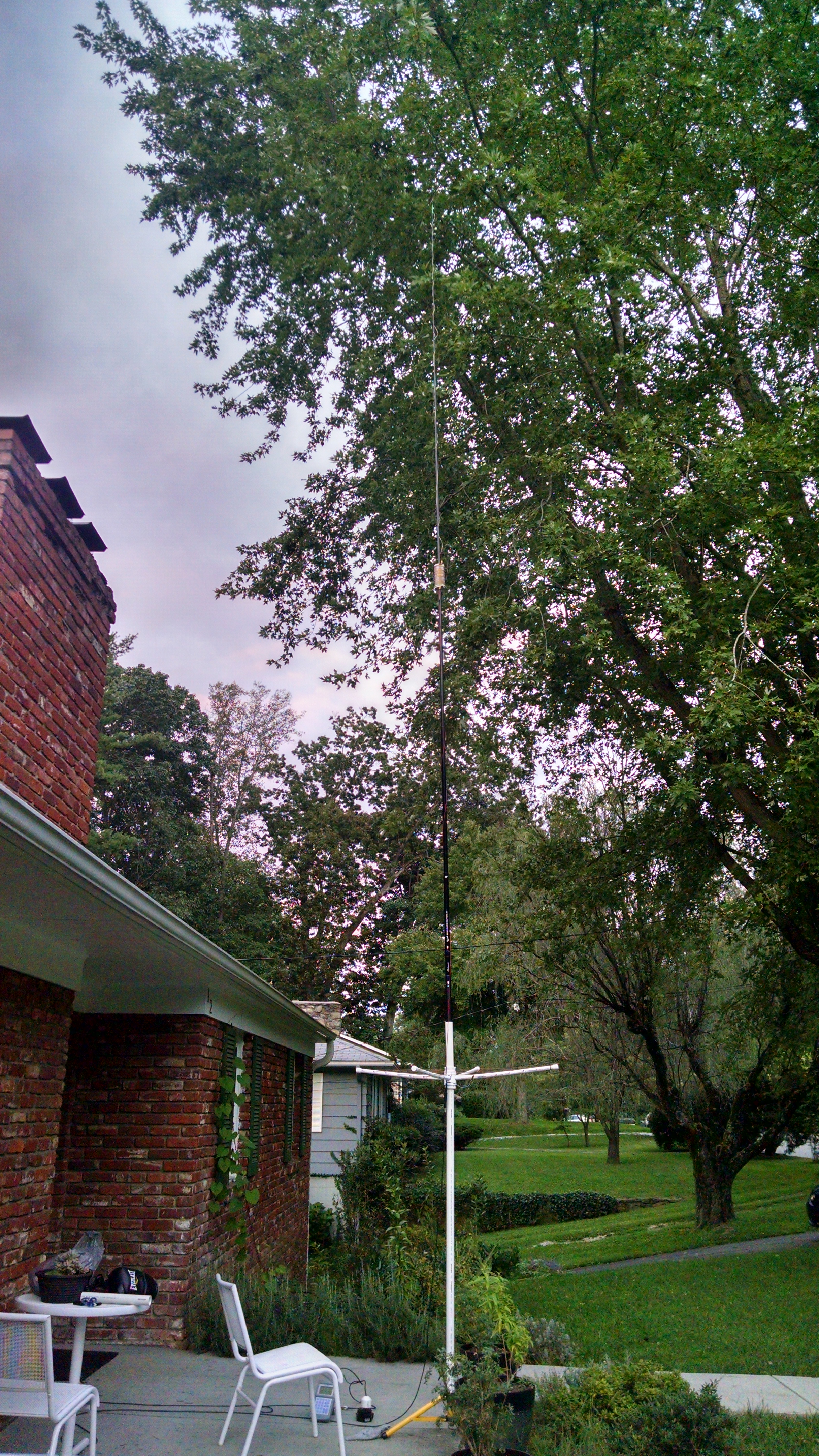
Completed Counterpoise installed and tuned

Complete Antenna
The counterpoise is a large square coil made on a 1/2 inch PVC frame. Four legs of 1/2 inch PVC (each leg is about 21 inches long) are connected by means of a four-way coupling which is pinned within a drilled 2 inch coupling. A piece of 1-1/4 inch PVC pipe is used to hold the fishing pole mast on the top and provide a means to mount on the ground. 2″ to 1- 1/4″ reducers are glued into the 2″ coupling. The entire coil is 5 and 3/4 turns spaced at 3 inches between turns. The turns start at 5 inches from the center. I measured 3 inch spacings on one leg and then did the same on the other three other legs. On the other legs however, I shifted the 3 inch point forward 3/4 of an inch on each leg with respect to the previous leg in the the winding order. This way the wire gradually shifts outward without abrupt turn hopping. I used #12 bare wire -you will need at least 40 feet of wire to make the coil.
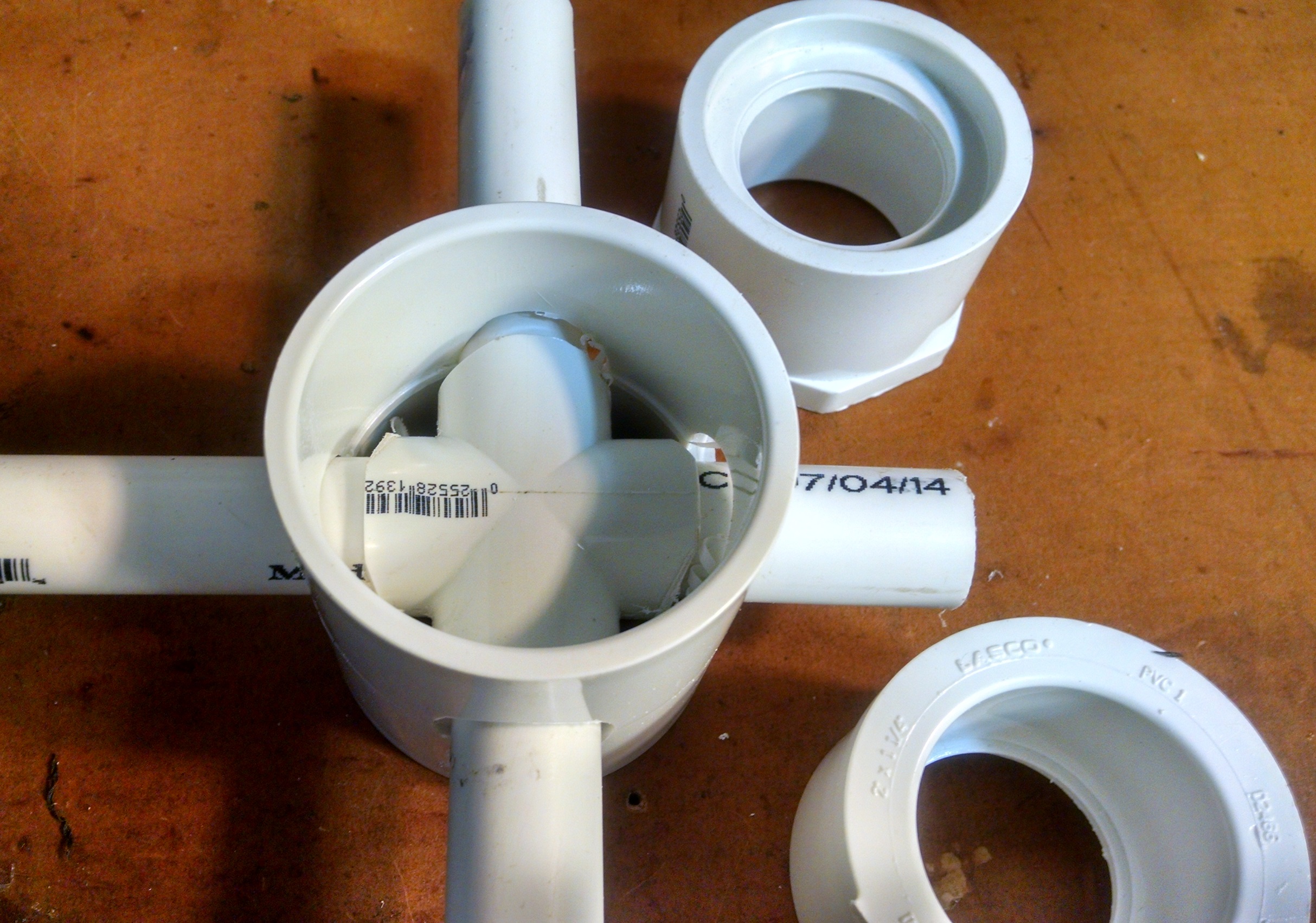
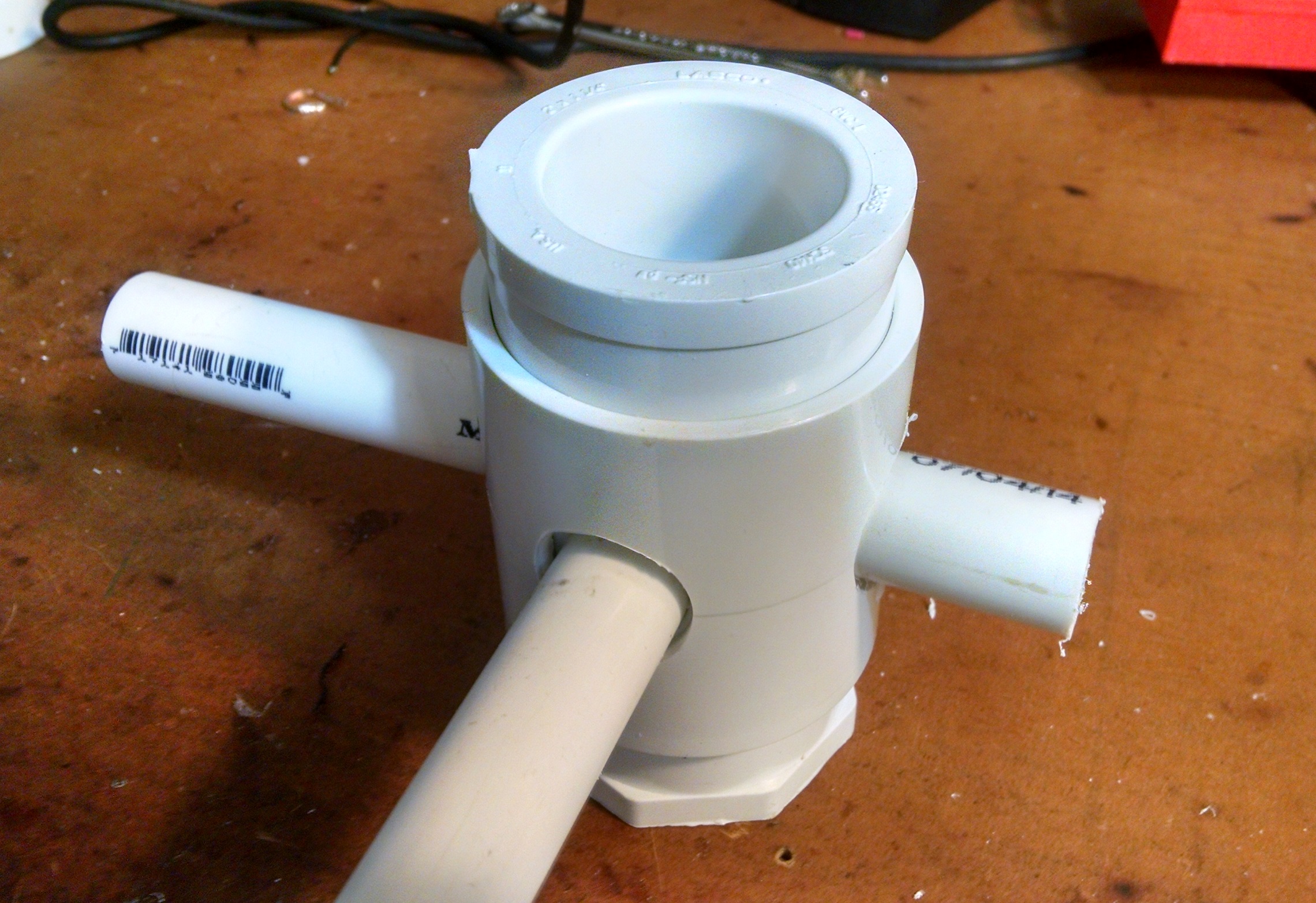
four way PVC coupling and drilled 2 inch coupling
(the four way has to be trimmed 1/8″ on the ends to fit)
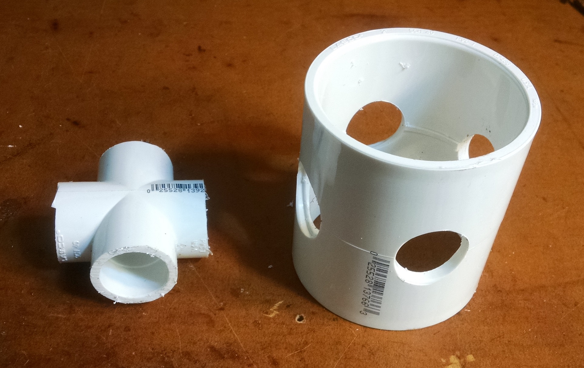
Coupling held in place with 1/2 inch stubs
1 1/4″ reducers are press fit and glued into the 2″ coupling

Glad to see your experiments with a spiral counterpoise. However, I tend to be quite suspicious of deriving efficiency from feedpoint impedance. I would suggest relative field strength tests, such as those that N3OX performed when evaluating his short vertical: http://www.n3ox.net/projects/n3oxflex/ . That could tell you with more certainty if you’ve really improved your radiated power by 30%.
I did some experiments a while back with a much shorter 40m vertical dipole (2m total, with high-Q air-core coils and large capacity hats) but concluded that on a concrete balcony, the losses were cripplingly bad (high-voltage capacity hats near concrete means lossy capacitive coupling to the environment).
I agree…feedpoint impedance for the radiator can be predicted with accuracy in ideal conditions – who knows in a real world situation like this….assuming the spiral is actually acting as a counterpoise???? the lower feed point impedance strongly implies less losses but field strength tells no lies. I will definitely do those measurements