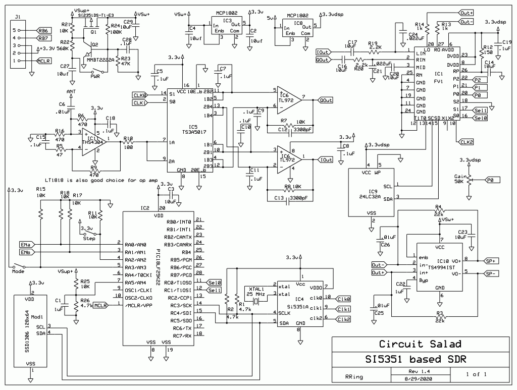
I have really enjoyed my FV-1 based mini SDR radio but it has one problem…its too small! I made the thing so small; it’s hard to operate and assemble. So I decided to make it a little larger, allowing for all the controls to be larger and more spaced out. It has a larger display and the circuit board layout provides for the switches, encoder, volume control and display all to be soldered directly to the board. All of the circuit components are now on the top side of the board as well. Along with these physical changes, I made some minor circuit changes. These include: some component value changes, a different microcontroller, clocking the FV-1 at 48Khz with the third output of the SI5351 and adding a on/off power circuit which utilizes a momentary switch instead of a latching one. It now has a built in flat pack lithium ion battery that can be USB charged. I also refined the DSP demodulators and I am now utilizing a weaver demodulator for USB/LSB.
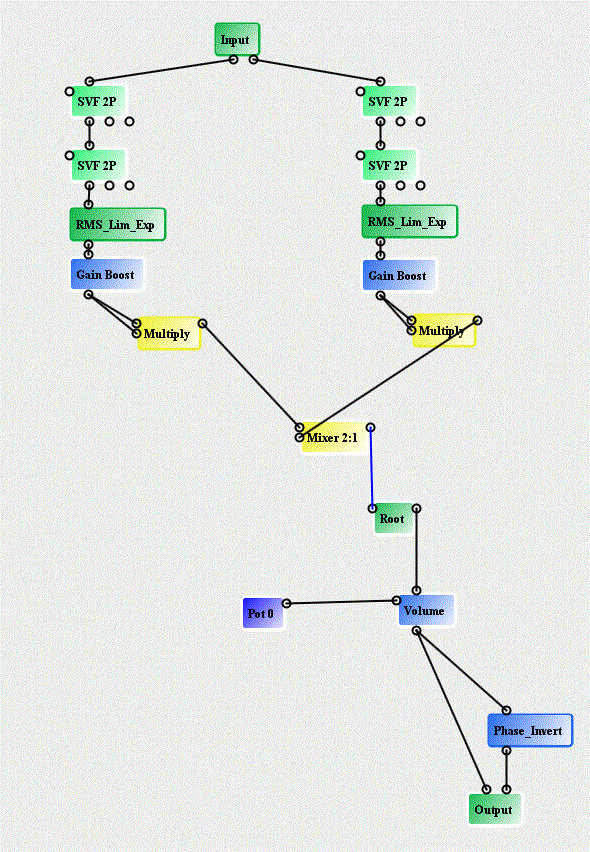
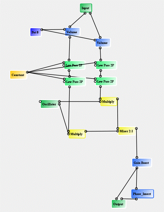
I started using a simple graphically based CAD tool(SPINCAD) to develop the demodulator DSP code for the FV-1, and I have been able to improve my demodulators algorithms. The CAD tool is free and is Java based. It runs natively in windows with Java installed. You can wire together functional building blocks and generate the required hex code for the FV-1 without writing any assembly code.
Examples of SPINCAD Graphical Programs
Link To Tech Data:
https://www.adrive.com/public/rPpBxR/MiniSDR%20Tech%20Data_11_2020.zip


