Below is a video showing the restoration of a 1966 Fender Deluxe Reverb Amp that has sat unused since the 70’s and was barely used over its life. Not much had to be done so almost everything is original…including the tubes! It sounds fantastic and looks like new.
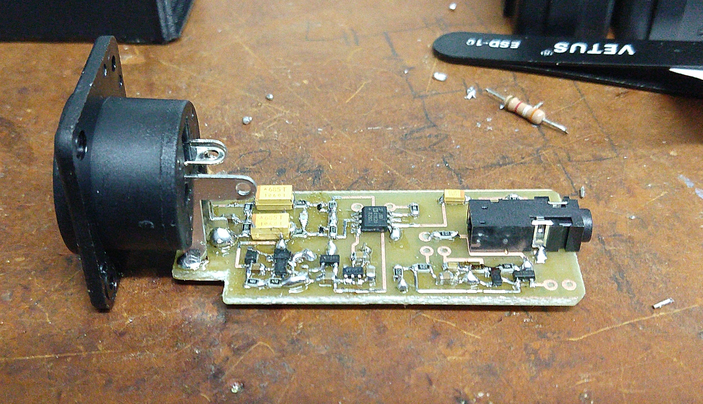
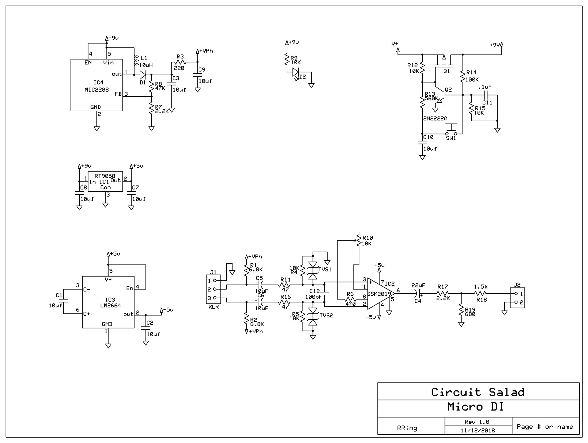
I frequently use my phone to record video for my blog and for my music projects…but I have been frequently frustrated by the limitations of the internal microphone embedded in the phone. So I created this circuit to provide a means to use a high quality Dynamic or condenser studio microphone with my phone. The circuit operates from a rechargeable 9 volt battery and plugs into the standard 1/8 inch four ring audio connector. It provides phantom power at 28 volts…which works fine …you typically don’t need 48 volts It utilizes a SSM2019 balanced microphone preamp IC, operating from a dual polarity charge pump power circuit at +-5V. At the output you need to provide a 2.2k resistive signature such that the pone can detect the microphone connection. The circuit also employs my simple momentary latching switch circuit which I often use and is described here at circuitsalad. Everything about the circuit is straightforward but the phantom power over voltage protection circuitry merits discussion. Basically, the isolation capacitors C5 and C6 are slowly charged up by the phantom supply but depending on what is plugged and unplugged can be be discharged very rapidly into the preamp input circuitry. This will be destructive and requires circuitry to shunt this energy to ground and dissipate it. This is accomplished by means of TVS1 and TVS2…which are prepackaged back to back zener diode. However the issue arises that simply using large zeners or transorbs is not a good idea because they have large reverse bias junction capacitance…which creates distortion as it modulates. To prevent this, I chose a very tiny 9 volt transorb. The one I chose (DF2B6.8ACT.L3F) has only a few pF of capacitance and is very small(402) surface mount package. The device works great but can only sink 1 amp peak. This further requires series resistors R11 and R16 to help limit the surge current to less than 1 amp at 28 volt. R1, R2, R4, and R5 must all be precisely matched in order to maintain circuit balance. R4 and R5 are required to provide a absolute ground reference such that the output does not float to some common mode DC value above 0 volts. The gain of the preamp is -6dB -20dB and is adjustable by means of R10. The reason for the negative gain is the use of an attenuation network that also provides the 2.2K resistive signature for microphone detection. The attenuation is required because of the inherent gain of the phone circuitry, which is easily overloaded.
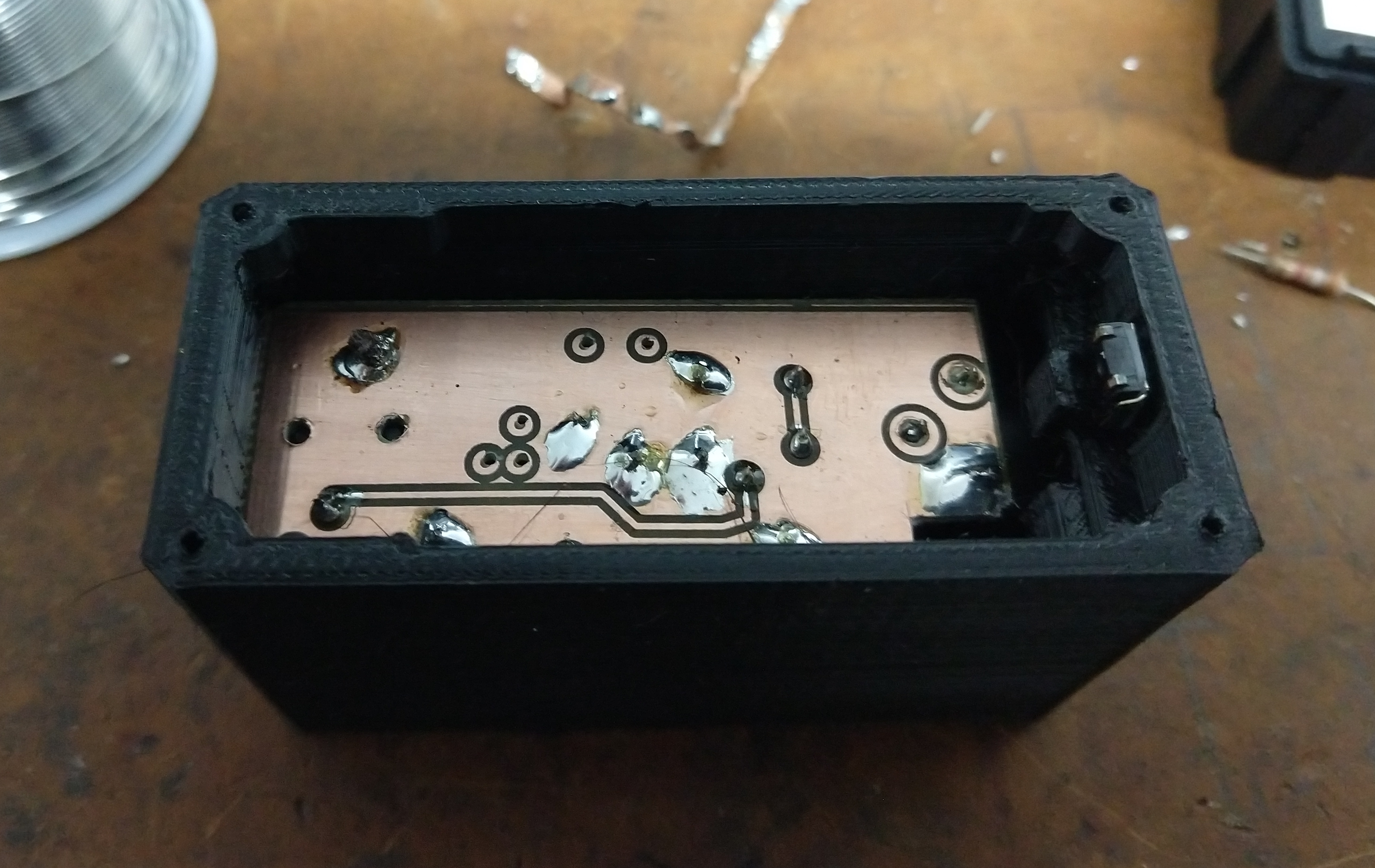
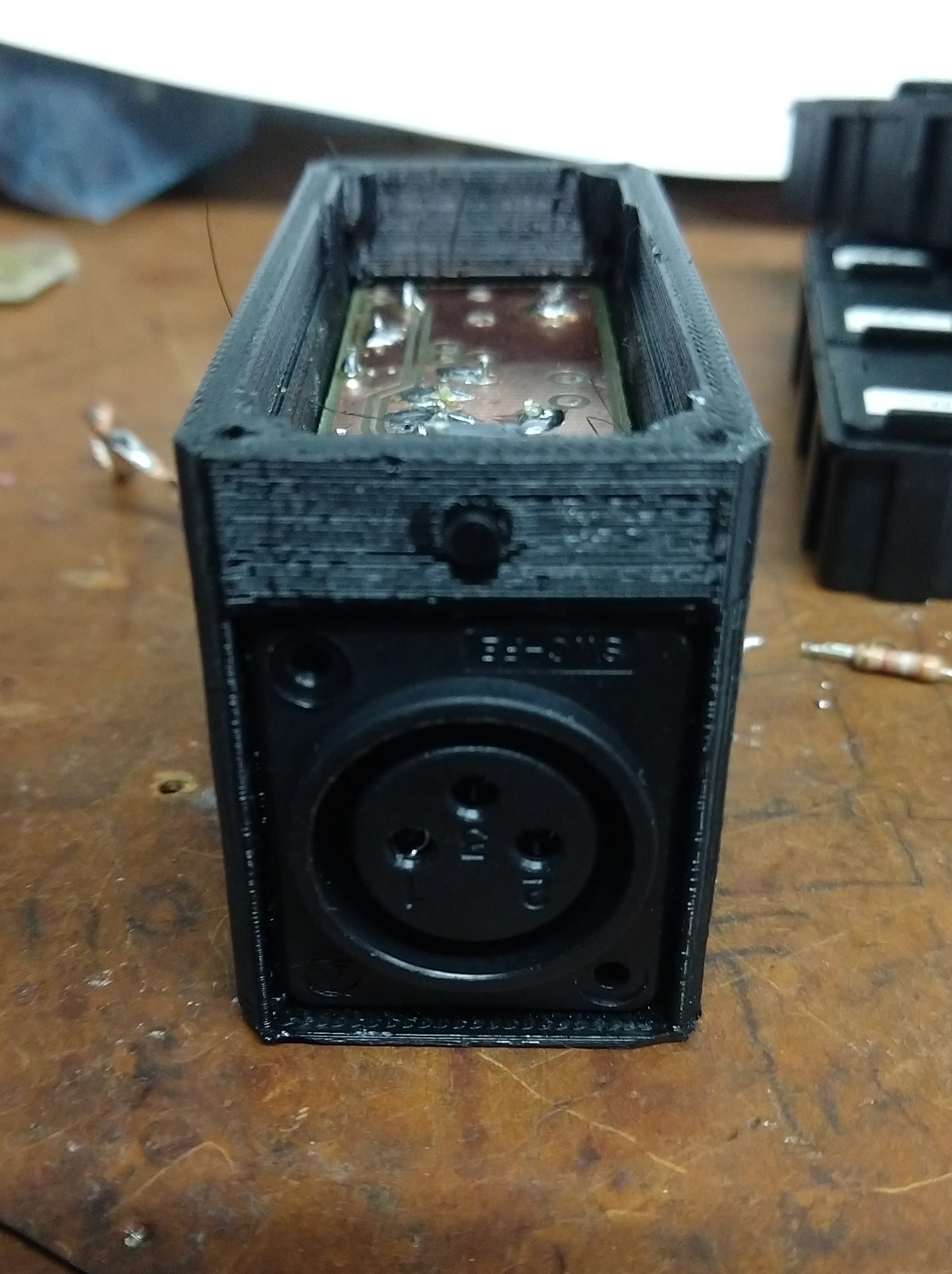
As seen in the pictures below, the circuit board fits in a compact 3D printed enclosure. The battery sits above the circuit board and is enclosed by a a top cover. I use a rechargeable 9 volt because the device draws about 30mA in total.t I included a 2.5mm circular power plug as a charging jack such that the battery can be charged without removal from a generic 9 volt battery charger.
but with an enhanced tone stack much like that of the Polytone Brute amps and a JFET driver stage for the final. The normal/bright selector is quite useful as well depending on the pickup type and location.
Here is a download link for the schematic and PCB in express PCB format(can be converted to gerber using freeware: copper connection)
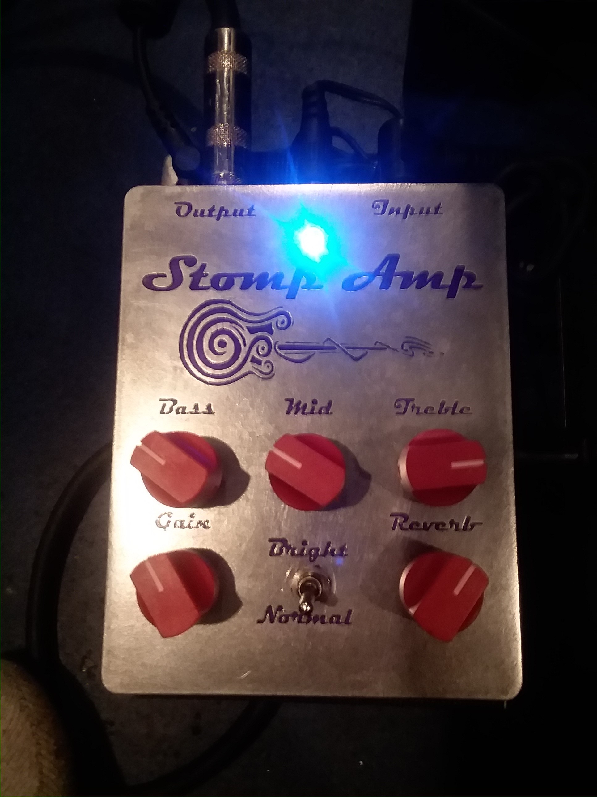
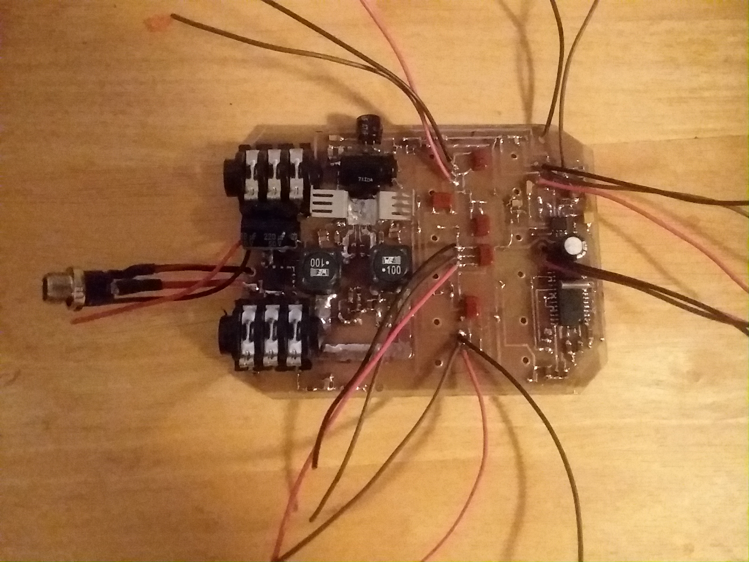
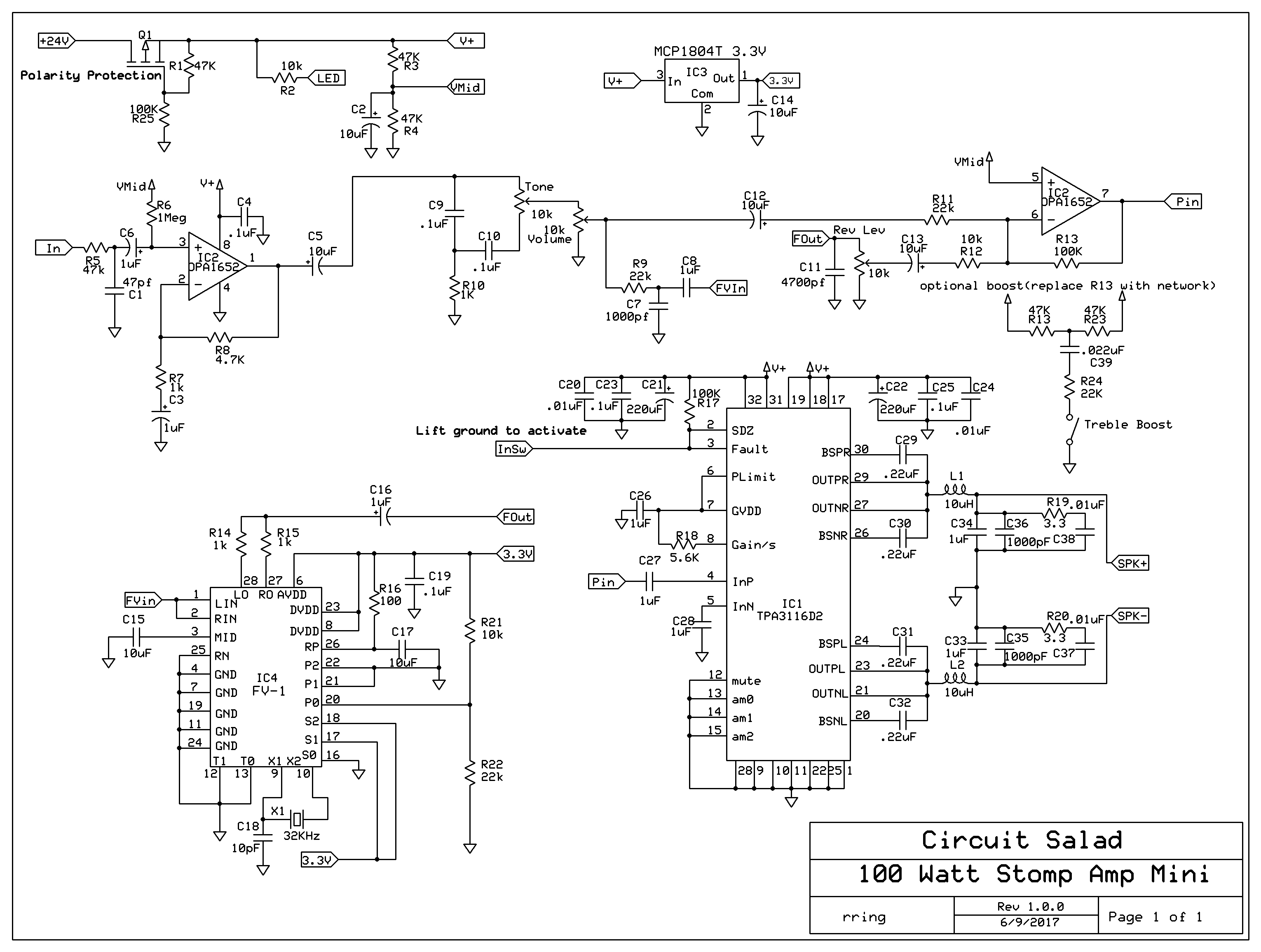
Continuing on my Stomp Amp theme; I have created a 100 watt (24V supply, 4 ohm load) guitar amplifier with FV-1 based DSP reverb and optional treble boost. It fits in a 1590b stomp box. Yes it really is a 100 watt amp!
It has Gain, a single tone control, and reverb level control. The reverb room size is set by a resistive divider(R21 , R22) and can also be made adjustable. It utilizes a TPA3116D2 class D amplifier IC which can be configured for mono or stereo output.
The amplifier sounds delightful. The class D topology provides greater than 90% efficiency. This eliminates the need for substantial heat sinking. The only penalty is that for guitar applications, pushing the amplifier to distortion does not sound so great. I use an overdrive pedal so I don’t care about this.
Update: I added a LED clipping circuit to make sure the input into the class D final amplifier is level limited(clips/distorts) before the final amplifier starts distorting
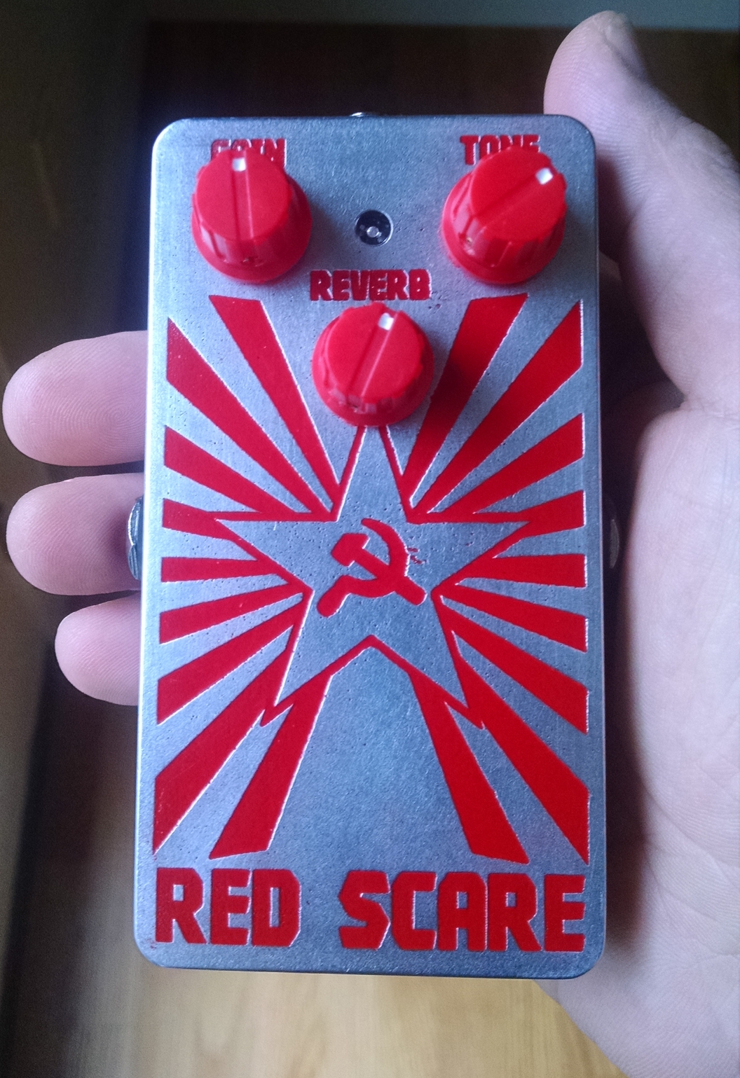
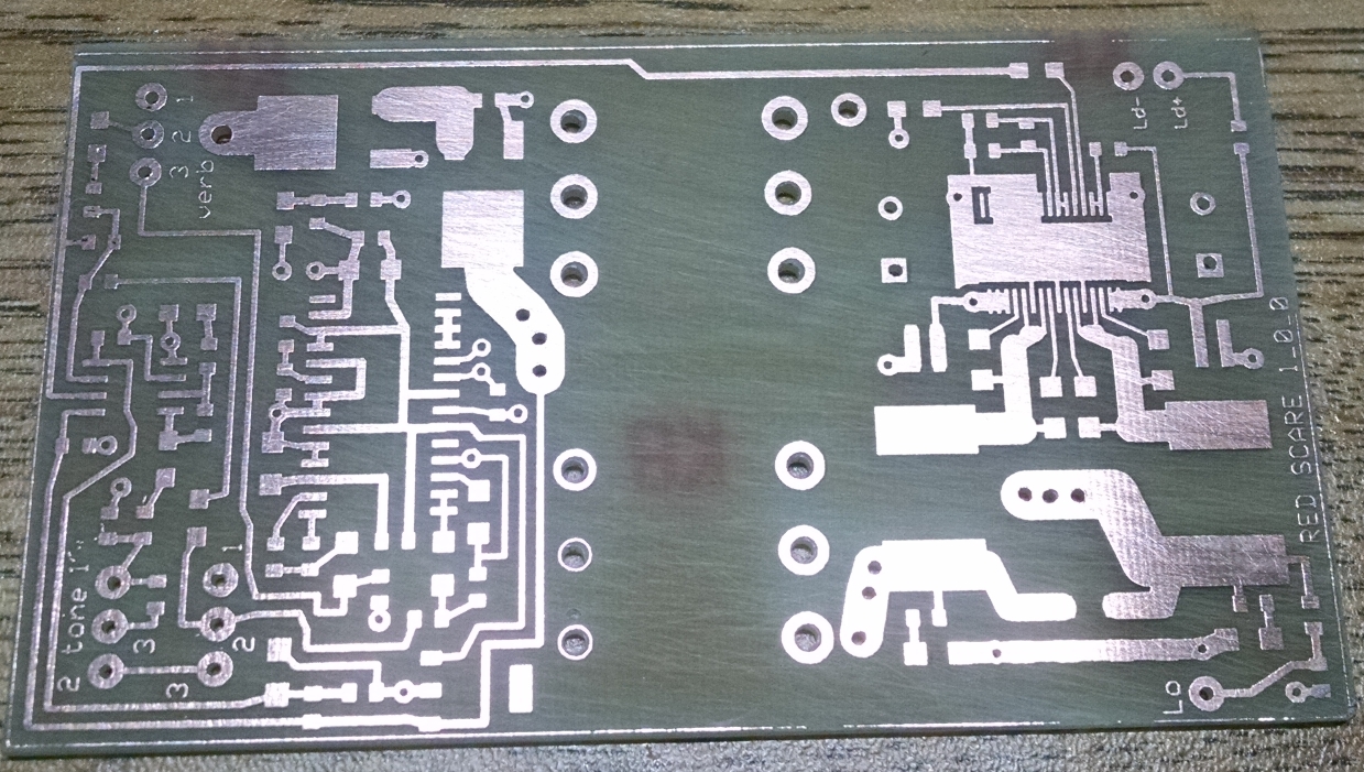
Link To CAD FILES: https://www.adrive.com/public/QpRQMX/RED%20SCARE.zip
The single tone control is surprisingly versatile. It alters the level and center of a MID scoop. You can get really FAT all the way to bright twang all with one control. The circuit can easily be modified to employ a more sophisticated tone stack if desired. The amplifier requires a 12-24V power supply with at least 4 amp sourcing capability. You can purchase a small lightweight switch-mode supply from Amazon for less than $20.00 that will work nicely. It is ridiculously small, lightweight, loud as hell, and sounds superb through a couple of 10″s or a single 12″ cabinet.
Quick Demo of built in Blue LED clipper limiter added to original prototype(you can see the LEDs flash as the input is clipped)
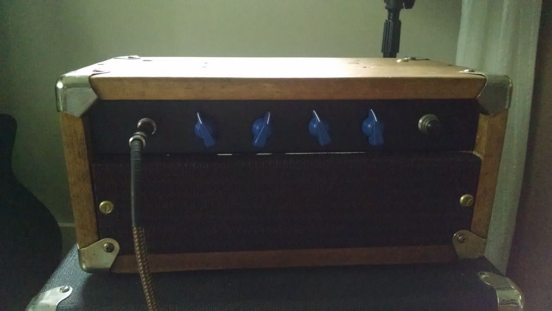
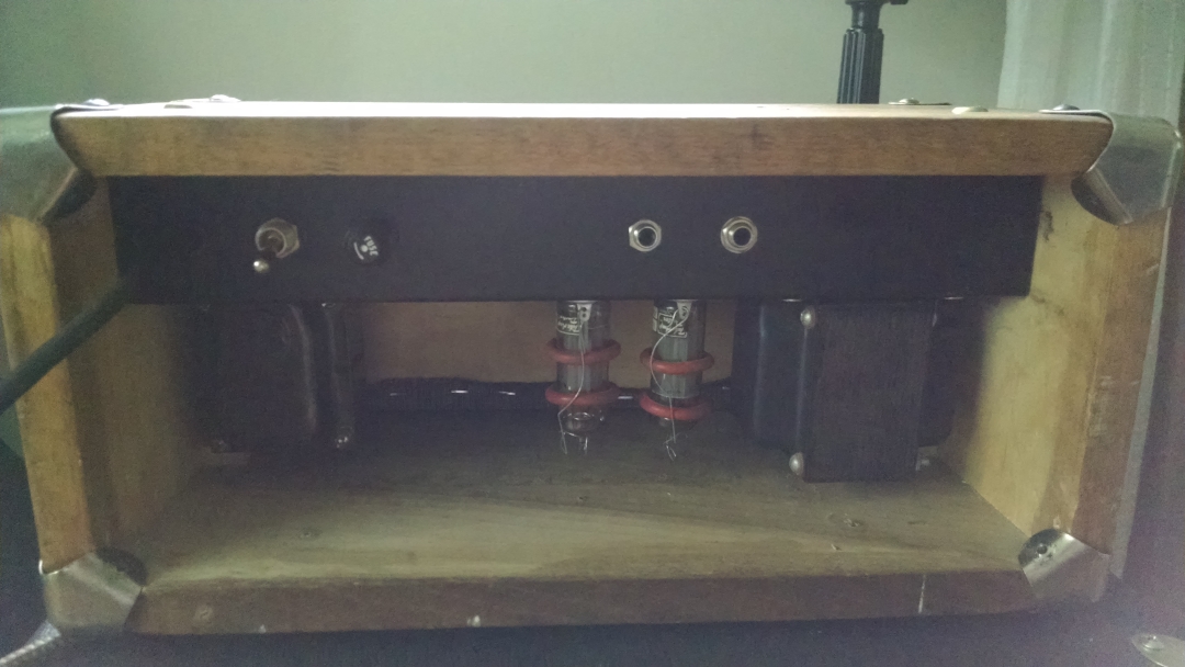
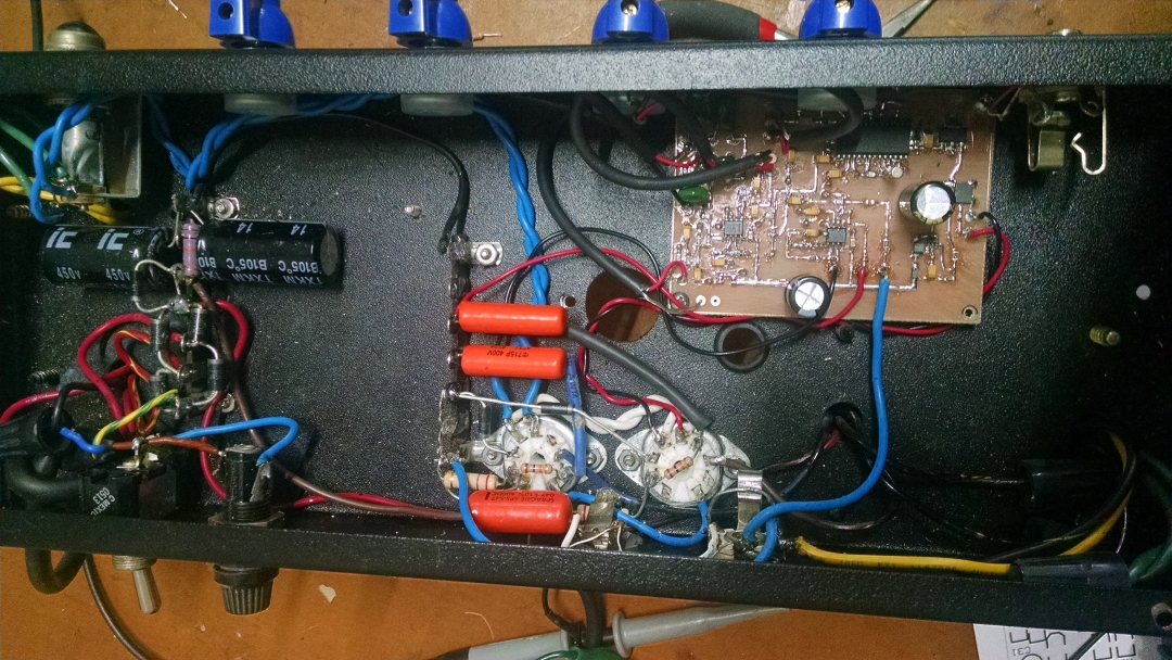
This is my new hybrid guitar tube amp which utilizes a solid-state input stage, DSP reverb, and solid-state phase splitter. Only the push pull, class AB output stage utilizes tubes, namely two EL84’s run at 390 volts with cathode bias. The bias uses two 15 volt zeners which creates a bias current of about 26mA. This requires almost 30 volts of swing on the grids to drive the amp to saturation. This is accomplished with a little switch mode boost converter that generates 29 volts to drive the phase splitter opamps. All of the solid-state circuitry runs off the AC filament supply for the tubes. The solid state portion is basically my stomp amp design( also on this blog) minus the final power amp, which is replaced with the phase splitter.
A couple notes about the design: Using zeners works great, but they can fail(haven’t had a problem yet) and typically they fail by shorting(very bad for the tubes!)..so it may be prudent to parallel with 1k ohm resistors and .1 uF caps to make them more tolerate of current or voltage spikes. I use 5 watt zeners and have yet to have one blow on me with numerous amp designs.
Also the gain distribution is not ideal. This is because of the low headroom of the FV-1 reverb IC which runs at 3.3v. This requires that there be lower gain in the first two stages than is possible – degrading noise figure somewhat. Despite this, the amp is very quiet – even with noisy un-bypassed zeners in the final bias circuit.
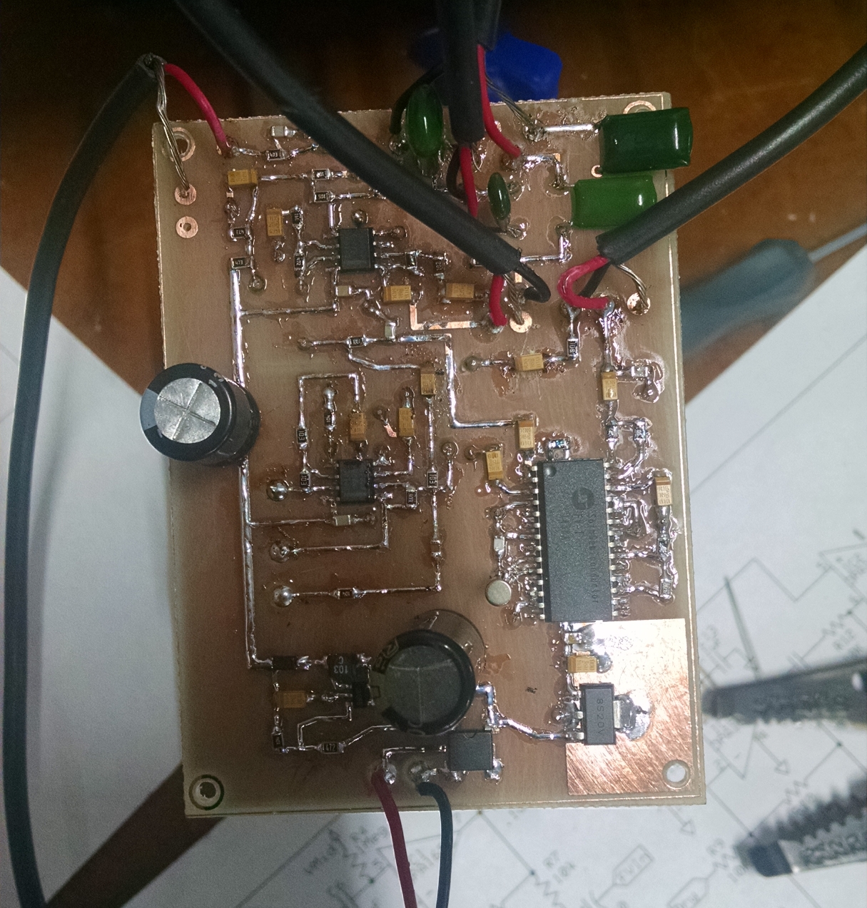
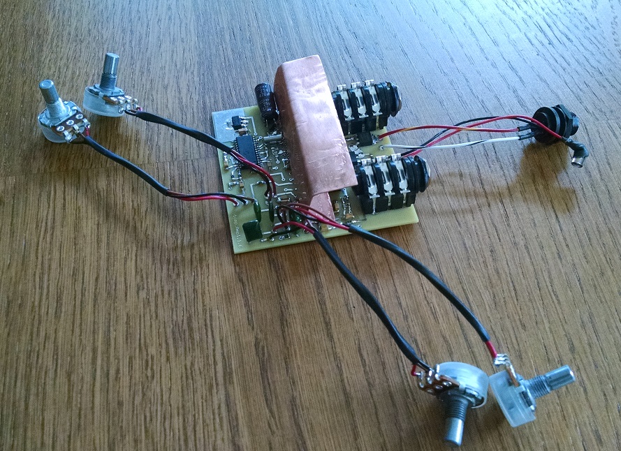
This is an idea I have had for a long time and I finally designed one. The results are excellent. The amp uses a surface mount car stereo power amp IC and can produce 25 to 30 watts with a 16V-18V supply into a 4 ohm speaker. The circuit fits in a 1590bb enclosure and has Reverb, Bass, Treble and Gain controls. The tonal response is tailored for guitar in the OP amp stages, along with the James/Baxandall tone stack. The James/Baxandall is a versatile choice because it provides boost and cut. I find it a better choice then the “beef stew” fender tone stacks. Reverb is provided by means of an FV1 DSP IC. It can be omitted easily if desired. The Power amp IC is bonded to the case to provide heat sinking when it is cranked up. I used a piece of 1/2 inch copper pipe -reshaped to be the heat sink. As I have done with some of my earlier amplifiers, I have employed negative feedback from the speaker back to a discrete stage driving the final amplifier. This is a common practice in tube amps to flatten the tonal response of the output transformers and so it is unconventional to apply it here. I find it affects the over all sound in a pleasing manner. The amount of feedback is small and could be increased or removed (this will affect the bias of the JFET Q3) All of the signal chains are low impedance (except the input) and gain distribution is such that the amplifier is very low noise. The amp powers up when the input is plugged in. The output is not ground referenced so the output jack is isolated from the case -(which is grounded via the heat sink). All you need is a tool battery or 12-18V power supply and a speaker cabinet and you can blast away. The mosfets used for polarity protection and power switching are just high current PMOS devices and not special – lots of other devices will work here. The op amp is a low noise type with a wide supply voltage range – others will work here also.
Things to consider when building:
The amp IC I used was a surface mount version – and I flipped it upside so I could bond a heat sink to the ground. there is also a leaded version available
Decoupling is critical – especially for power amp – the double decoupling caps on the schematic are one set at each of two VCC pins on the power amp
Capacitors C3 and C11 weight the amplifier to tonally for guitar – these can be changed making both 10uF for example will work fine. If you want to use a Bass guitar make C3 at least 4.7 uF
The passive tone stack was chosen to attenuate gain so that the FV-1 would not be overloaded. Other tone stacks can be substituted just keep this in mind if you use the FV-1
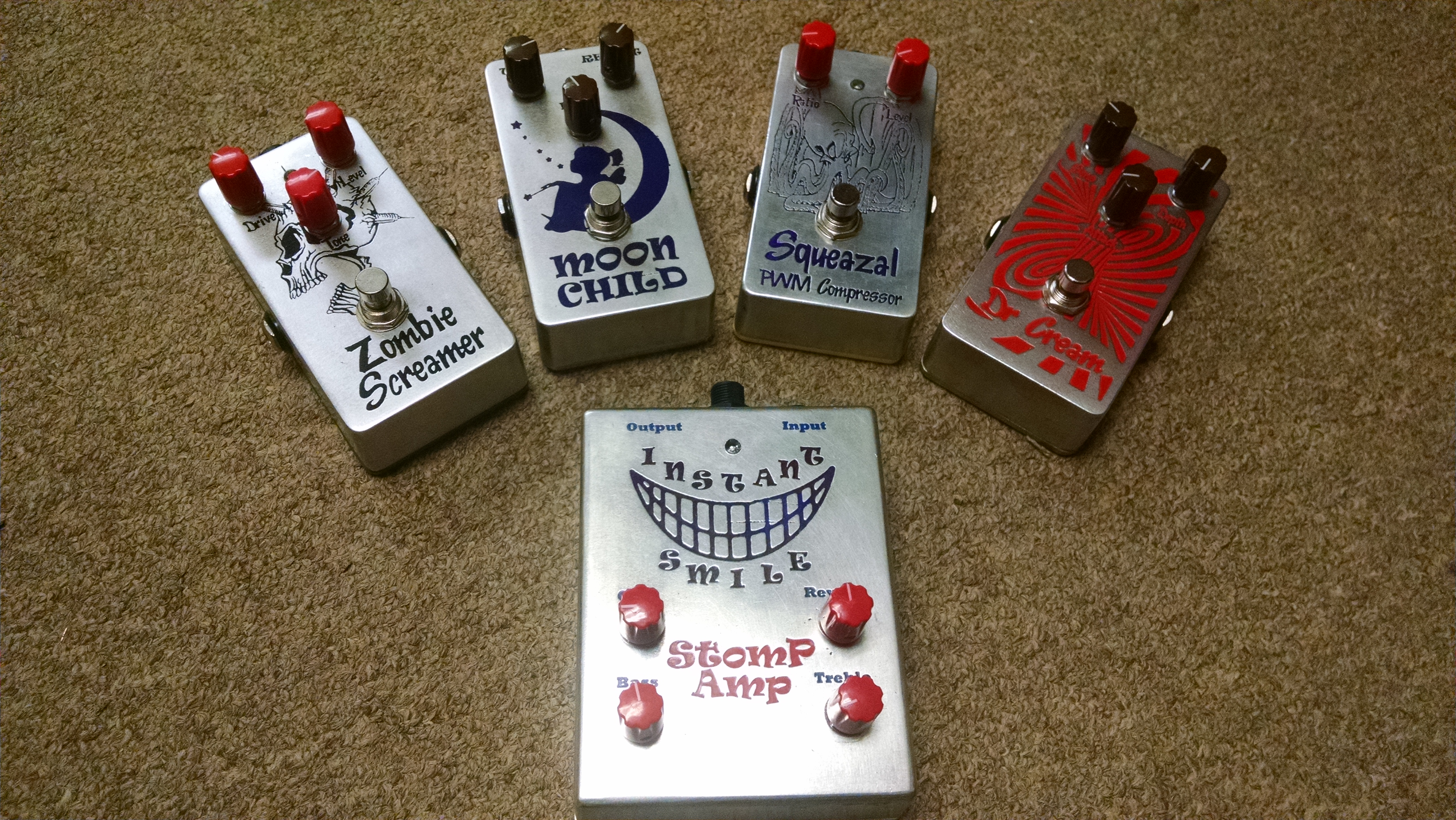
The Stomp Amp along with some other pedal designs of mine
I have thought for some time that by adding shunt/shunt feedback to a bipolar transistor or mosfet (a JFET also but only AC coupled), that it would emulate a Triode tube with respect to the output I/V curve. So I decided to simulate it and check. These devices, when biased for normal operation, have a output response that becomes independent of the supply used. This is the same for a Pentode tube like a 6L6, EL84, etc, where the screen grid has a constant bias allowing the plate voltage to vary significantly without changing the current flow through the tube. By adding shunt/shunt feedback, which in this case is a feedback resistor from the collector to base of a Darlington device, the output I/V behavior becomes constrained by the biasing of the base and therefore affected by the changing voltage seen at the collector.
Shown below is a simple amplifier circuit, simulated in SPICE, using a Darlington but without the feedback. You can see from the I/V(current is the Y axis and voltage the X axis) curve that at a couple volts or so, the device is in the active region and as the voltage increases the current stay mostly the same. The current through the device becomes independent of the voltage across it – like a Pentode or saturated mosfet.
Now lets add the shunt/shunt feedback as shown below. You can see with the new circuit, that as the device is turning on, there is a small but highly non-linear region. This is because the supply voltage is below the point of actually biasing the device all the way on. As the supply voltage is increased, the device is biased on but the current through the device now is dependent on the supply voltage because as the supply voltage changes so does the base bias and therefore the current flow through the collector circuit. The alters the I/V behavior the device to act like a Triode where the output I/V behavior is much like a simple linear resistor.
I used the Darlington in the manner in my Battery Amp with excellent results.
I modified the circuit of the battery amp to put the volume control before the first stage like the original FET version of the amp (one of the first posts). It really doesn’t sound that different – It just allows you to have really high output input sources without overdriving the first stage. It is very easy to modify the original board layout to do this. On the final stage, I also modify some values because of the altered gain distribution.
Here Is The New Schematic showing what needs to be modified:
if you compare to the last version – its not that different.
Here is jazz demo with some compression from my simple opto-compressor and the amp set with a little mid size room reverb and mid way settings on the Bass, Treble and Presence. The guitar is a cheap beater electric that cost me $150.00. It is always fun to see if you can good sound out of crappy guitars!
Note: In the this schematic and layout below, I changed one of the select lines for the FV-1 to use a different reverb algorithm – not a big deal – I just like it a little more than the original.
Here is a new board layout that requires no modification and reflects the new schematic exactly:
Demo 2: Old beater electric guitar, small room reverb, lot of treble, bridge pickup and noodling around on B minor. As a side note: I am also using some compression with the newest opto-compressor described in a previous post.
I have one guitar that belts out a huge signal from the neck pickup. I was able to make the first stage just start to distort. To correct this, I have changed R5 to 1K and R3 to 4.7k also I have un- bootstrapped R4 and directly connected to ground. I thought the bootstrapping was a good idea – I must have eaten too many Twinkies that day. C30 and R29 are still optional but could be used to give treble boost or hi/lo gain boost etc.
If you have already obtained the earlier board rev, you need to cut the trace from the emitter of Q1 going to R4 and ground that side of R4 to the ground plane.
I am posted a link to the new board rev here and obsoleting the schematic and layout in the old post. All I did was eliminate this trace and add a couple of wire connection pads to allow making R29 a POT for variable gain. If you have the old board it will work just fine – with the mod described above.
Couple other minor notes: C16 may need to be increased to 22pF or so if you have a sluggish crystal – had one out of five that needed the bigger cap. Also with the mods above you may find that C21 should be increased to .22uF or more depending on the range and level of treble boost desired.


 Home brew laser printer resist circuit board
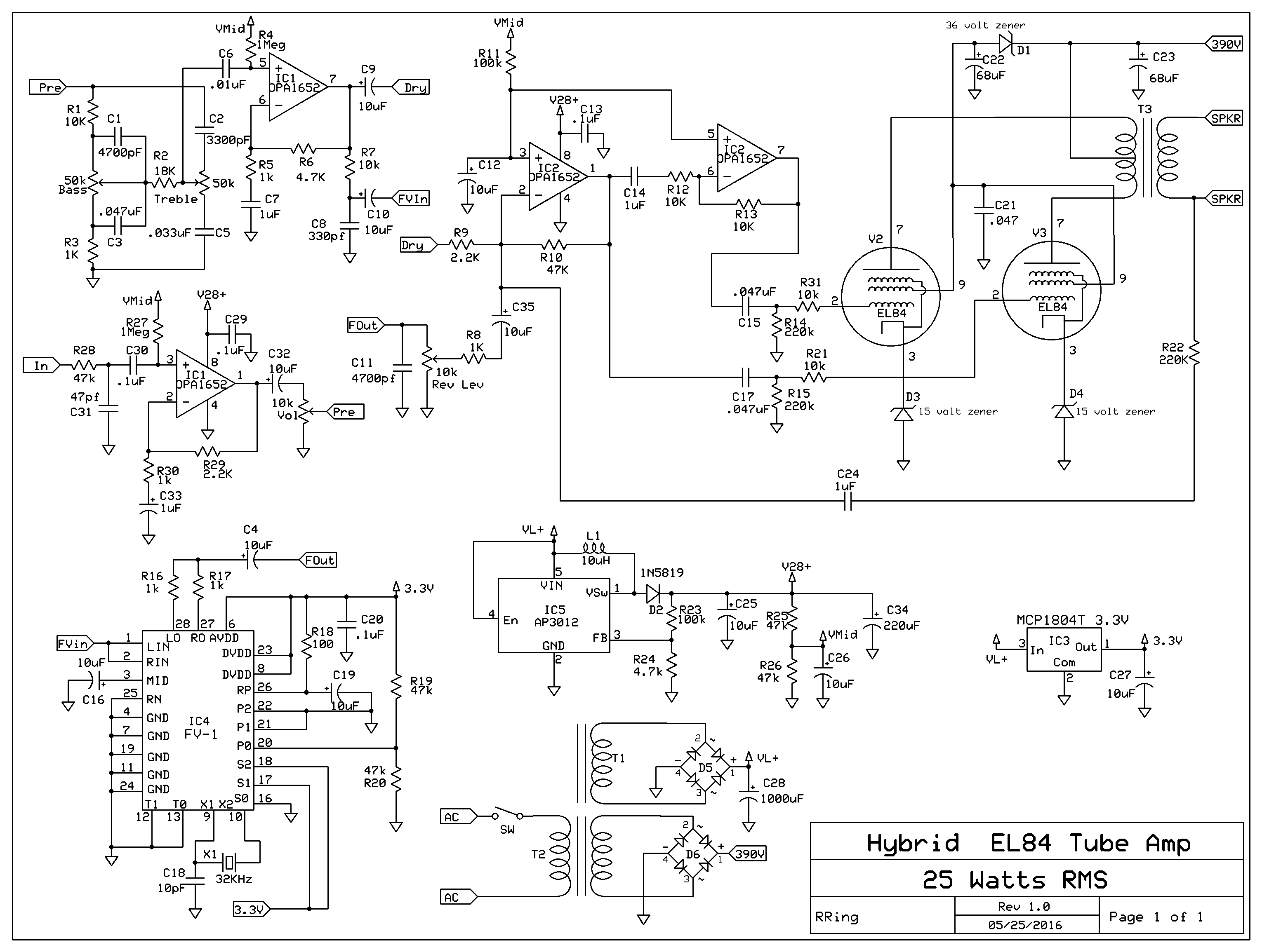
