
I am building a little QRP rig for the 40 meter band , utilizing one of my DC receiver designs. I am using a CS2000 clk generator for the receiver and can use the clock output to drive a 1 watt or so RF amp for the TX. I am prototyping the transceiver now and will post that design when it’s done. I designed a nice class E final at about two watts but it was tricky to test and tune…etc- so I thought I would come up with an amplifier that was easier to duplicate by other builders. This amplifier works well and is easy to build. It puts out in excess of one watt from a single 74AC240 (the 74HC240 will also work but not put out as quite as much power). You can also use a couple of 74AC04’s also. The 240 is convenient however, because it has an enable pin for keying when using CW. The circuit uses two sets of four inverters driven by a couple more inverters( to create differential inputs) and either a balanced L network(followed by a balanced to single ended combiner transformer) or a LC tuned balun to match the output to a 50 ohm load. The schematic shows both methods and values for 7 Mhz. I have created a spreadsheet for calculating networks for any band desired. The inverters have very low impedance and so you need to match roughly 4 ohms at the inverters to 25 ohms for each side of the push pull sets. You need to heatsink the inverter IC’s! I used a small heatsink for IC’s (seen on top of the 74AC240 TSSOP package) but you can use a piece of bent aluminum – or copper, etc. Because of the low Z, all of the matching inductors are small – so you can easily fabricate your own small air wound coils or coils wrapped on scraps of ferrite from junk inductors- you don’t need to have specialized toroid cores.
The LC balun works well but was trickier to get adjusted (needed further matching by means of a L network). The simple “sortabalun” transformer combiner in tandem with the balanced L network works a little better and is easier to design and adjust. The only disadvantage is you need some sort of ferrite core material for the transformer – whereas the LC balun method can be all air inductors. If you have some ferrite material – use the transformer method. One could do impedance transformation with the transformer but the L matching provides filtering, can be easily adjusted for parasitics in the inverters(capacitance) and a 1:1 transformer is very easy to construct!
The only drawbacks of this design are, one; you can only use 5v up 8V max to power the amp and two; it is not very efficient (mine runs at about 40%- 45%). It can draw .4 amps @ 8V – which is quite a bit of heat! Having said that, it is fun to build and tolerant of mismatched SWR. Overall, not bad performance. If you used two of them (8×8 push pull) you would need to adjust down the L network inductors and increase the capacitor(this lowers the impedance at the inverters further). I expect you could get more than 2 watts.
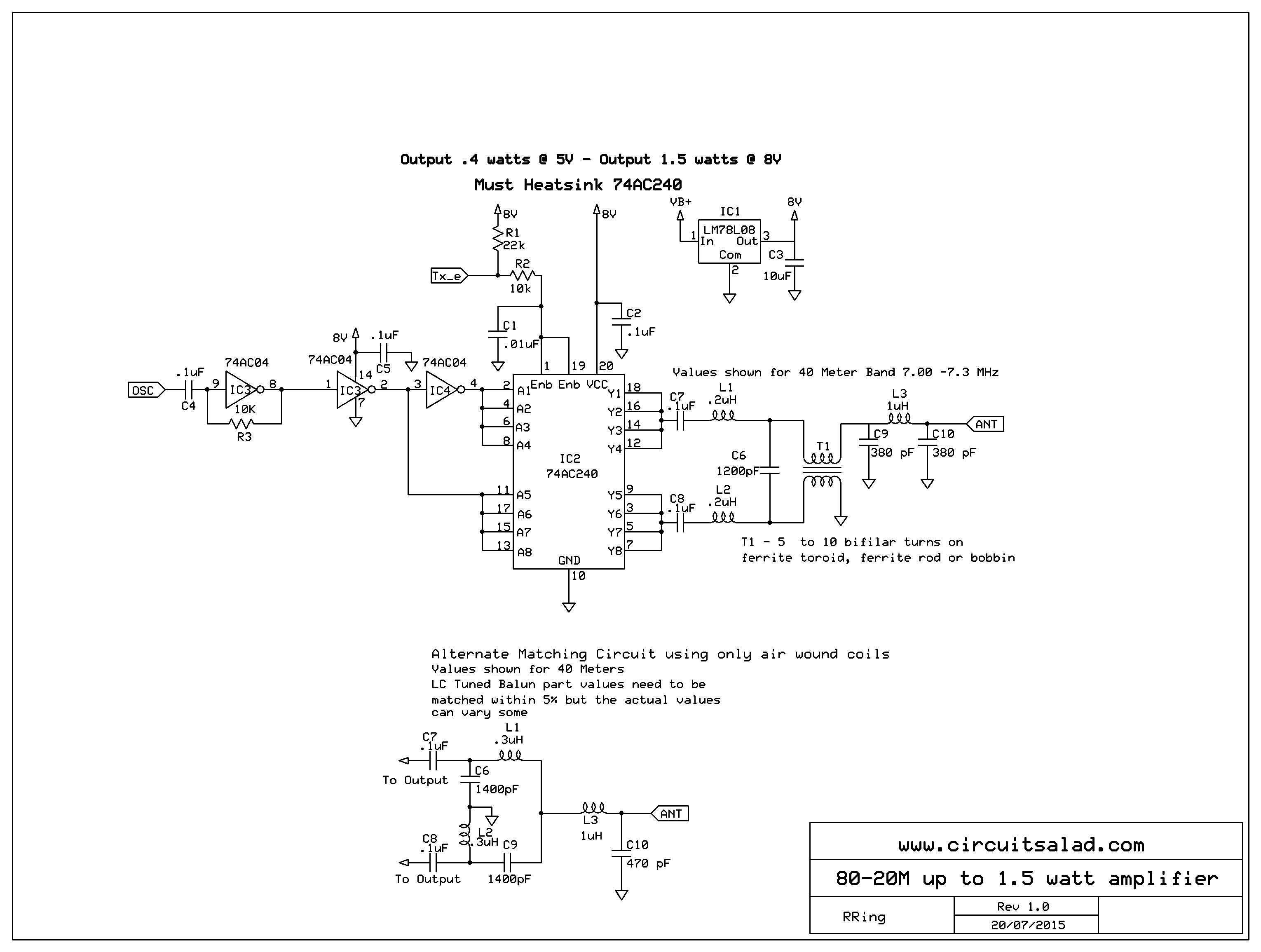
Schematic Diagram(minor revision 07/29/2015)
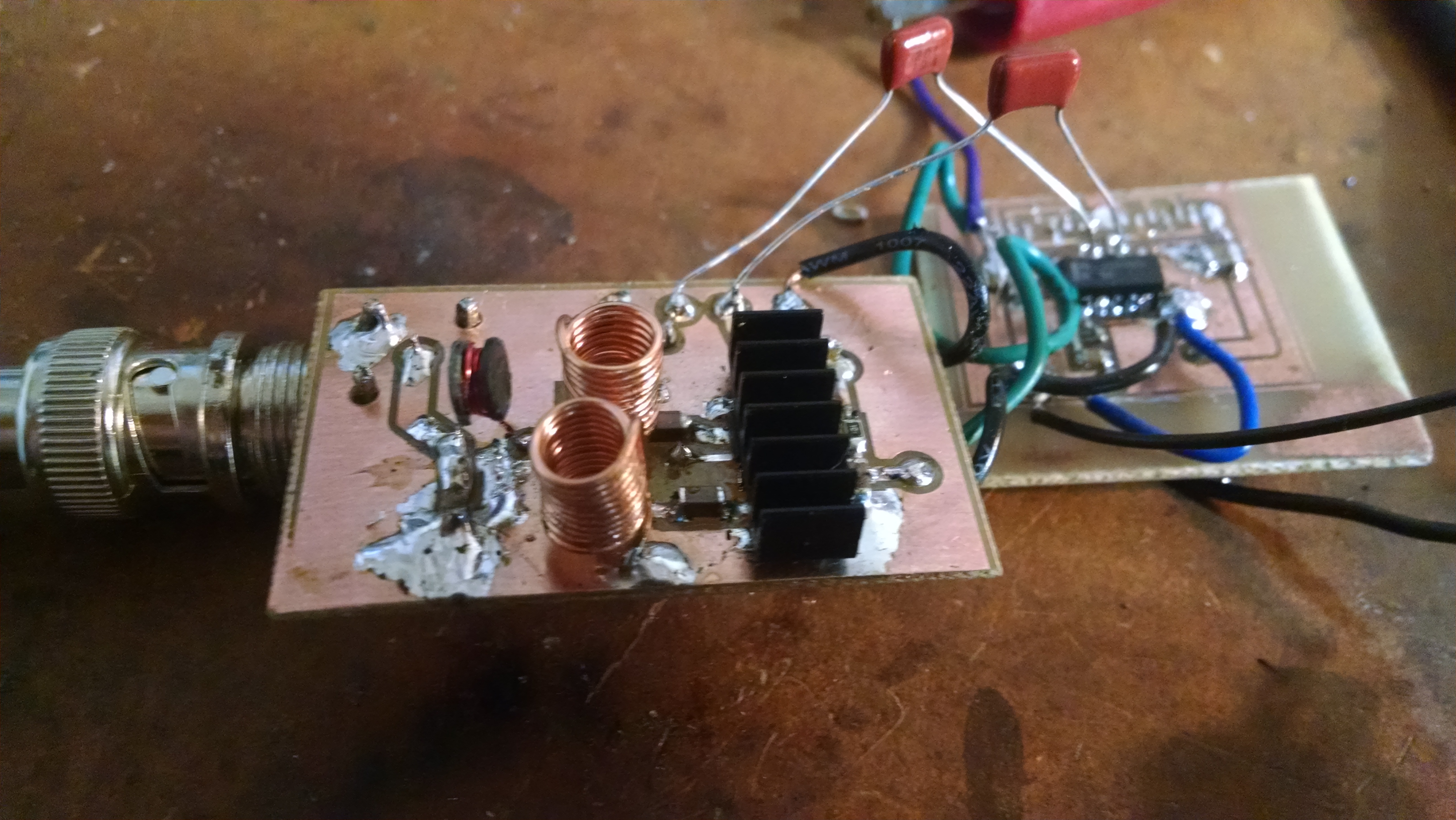
View of main amp using LC Balun
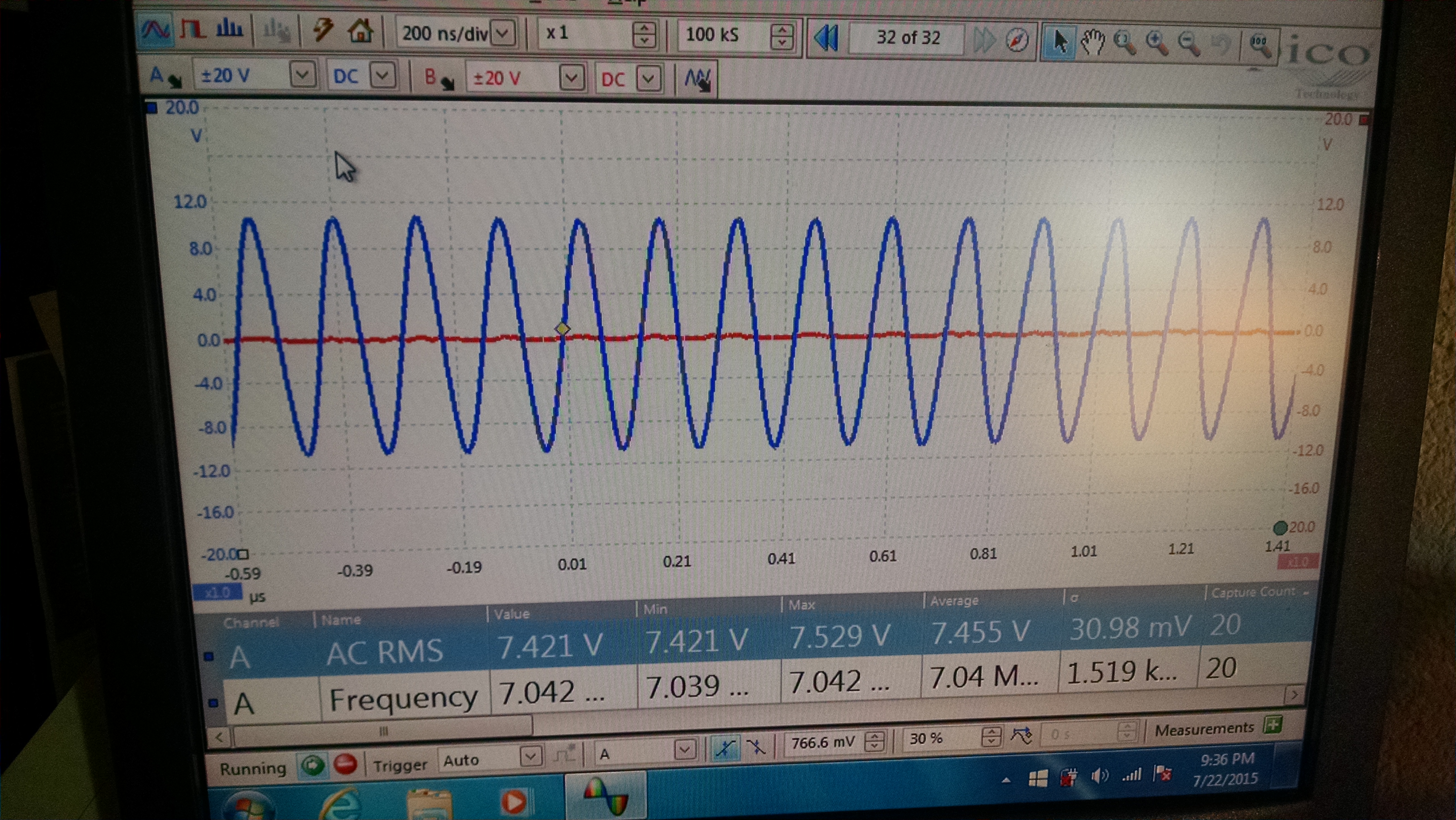
Just over 1 Watt 2nd and 3rd harmonic down 37 dB with LC Balun
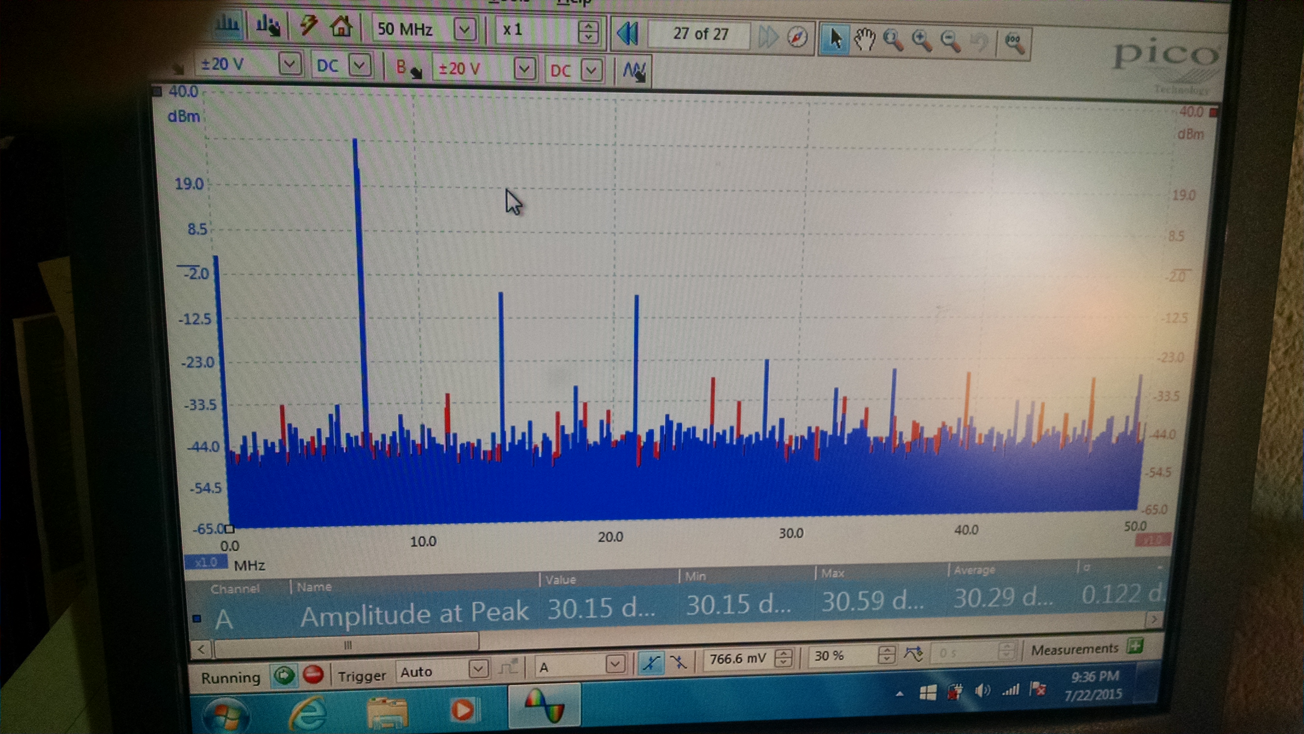
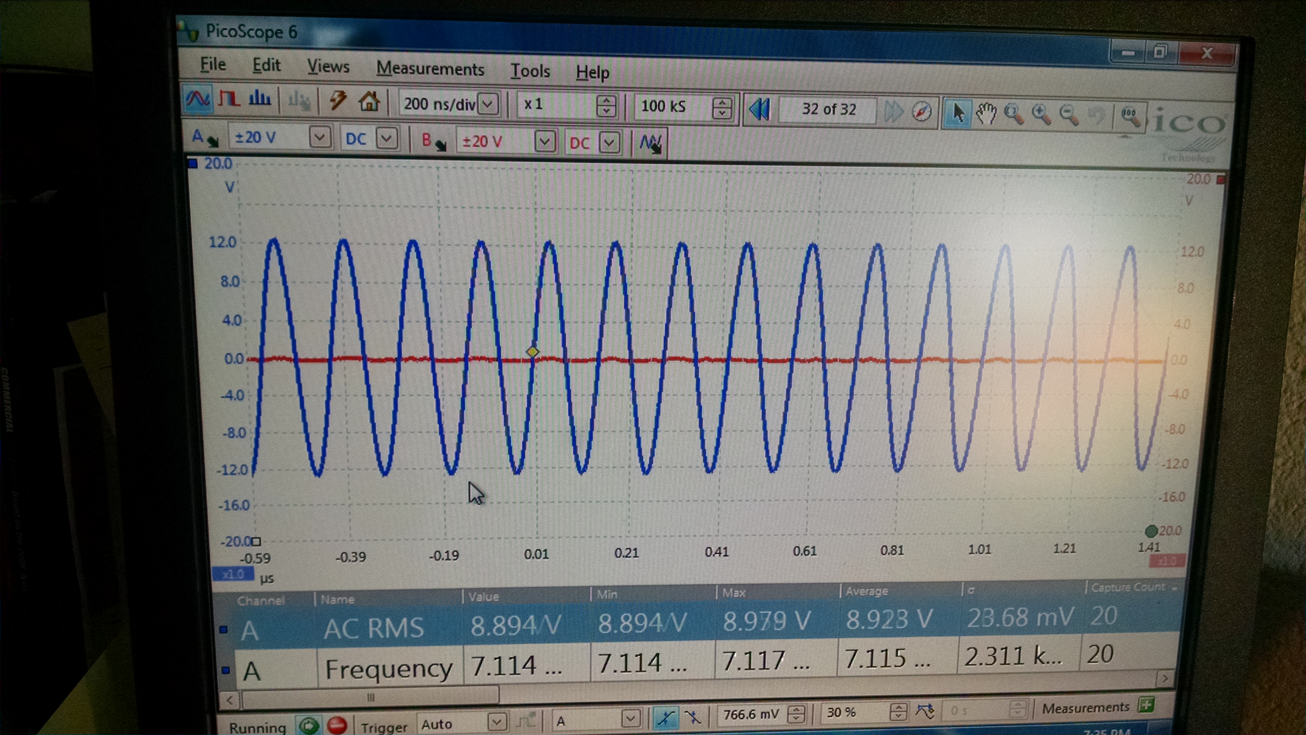
Over 1.5 watts with balanced L network and sortabalun!
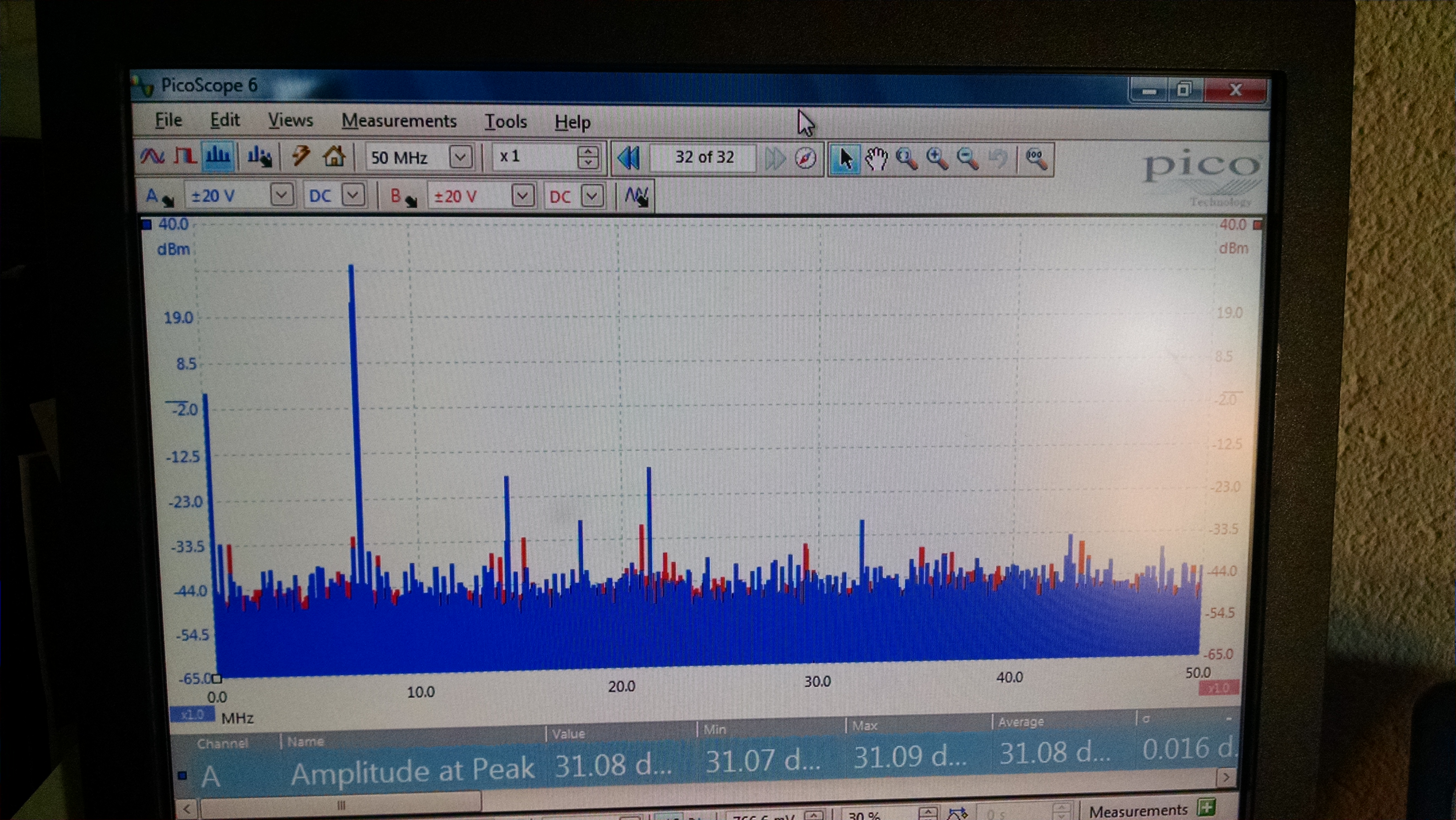
Harmonics down more than 40 dB!
Link to network designer spreadsheet: https://www.adrive.com/public/5wtBBr/network%20designer.xlsx
