
So I have been using the my center loaded 40 meter vertical with a spiral resonant counterpoise for a couple of weeks and can say it is performing as well (perhaps a little better) than with my 24 ground radials. I did some simple field strength measurements with a spectrum analyzer and pickup coil; at about five different positions and at various frequencies in the 40 meter band. I did this with the spiral version and with 24 ground radials. Comparatively, they were within a dB of each other. The spiral was about 1 dB better in three of the positions and both antennas were about the same in the other locations. However, this was only the case when the spiral was adjusted properly(less than 3:1 SWR).
I improved my loading coil by 3D printing a low density coil form and added a capacitive hat to improve the performance of the radiator as much as possible
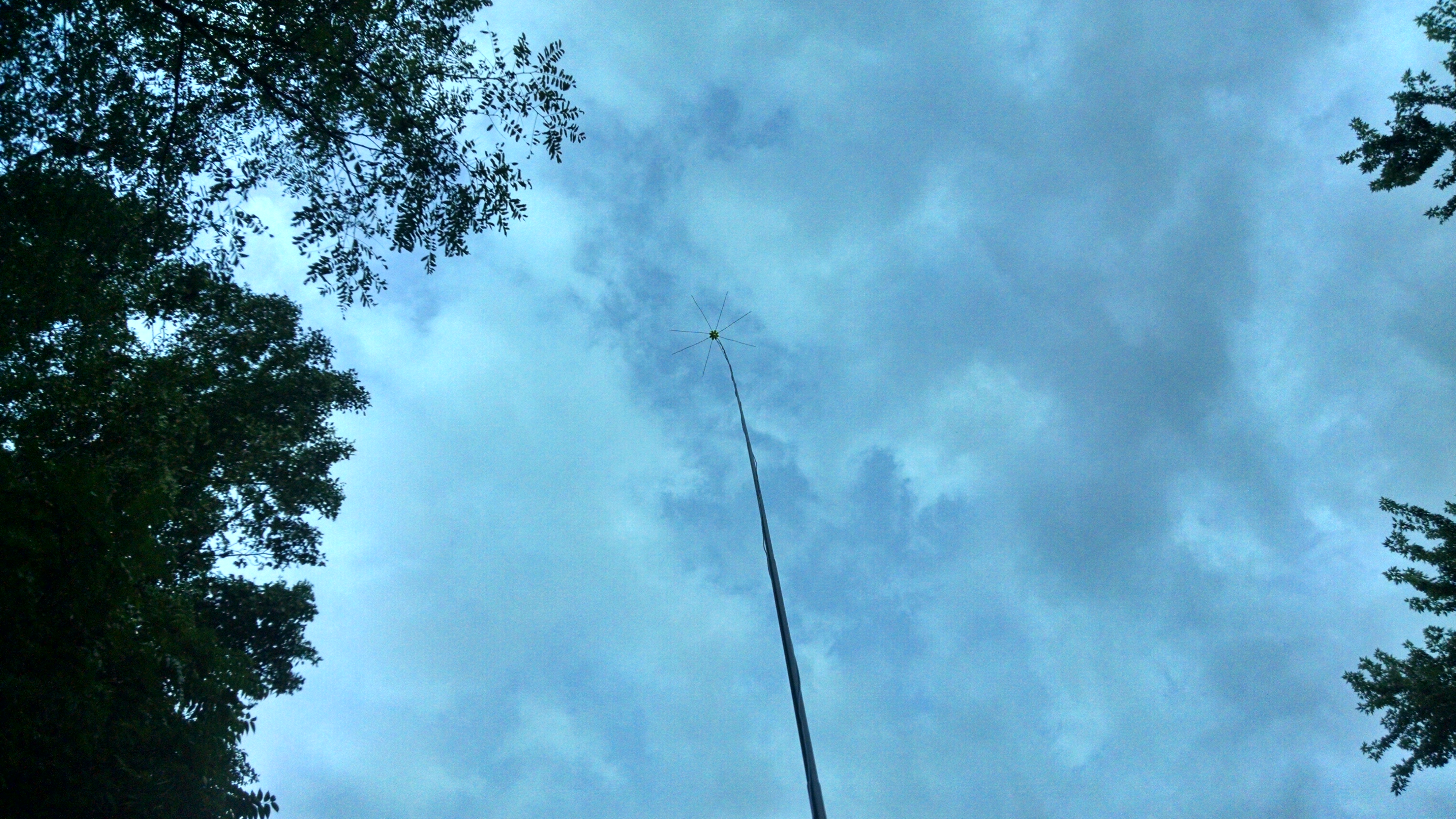
The 2:1 SWR bandwidth is small (50KHz) and if you move it around you need to retune it -so its more critical to adjust and less forgiving than when radials are used. The footprint is much smaller though and I have easily set it up in my driveway, on my deck, and over grass (about 5 feet off the ground). Generally, I am achieving the same range, signal reports and number of contacts as before. Using the spiral decreased the bandwidth of the antenna and lowered antenna impedance, while using the same exact 1/4 wave element I was using previously with radials.
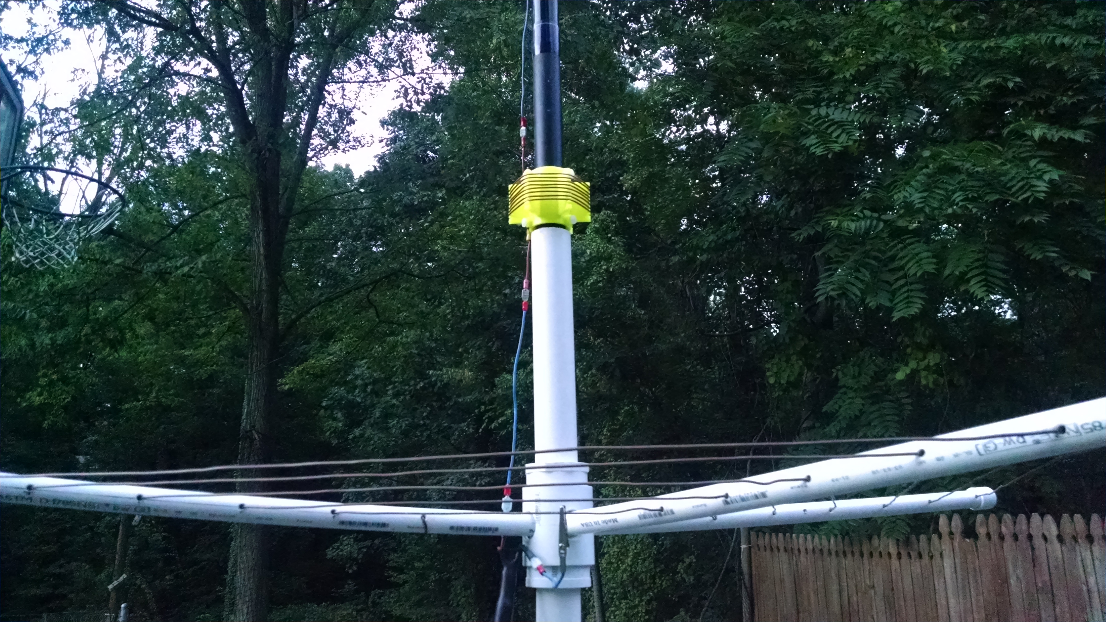
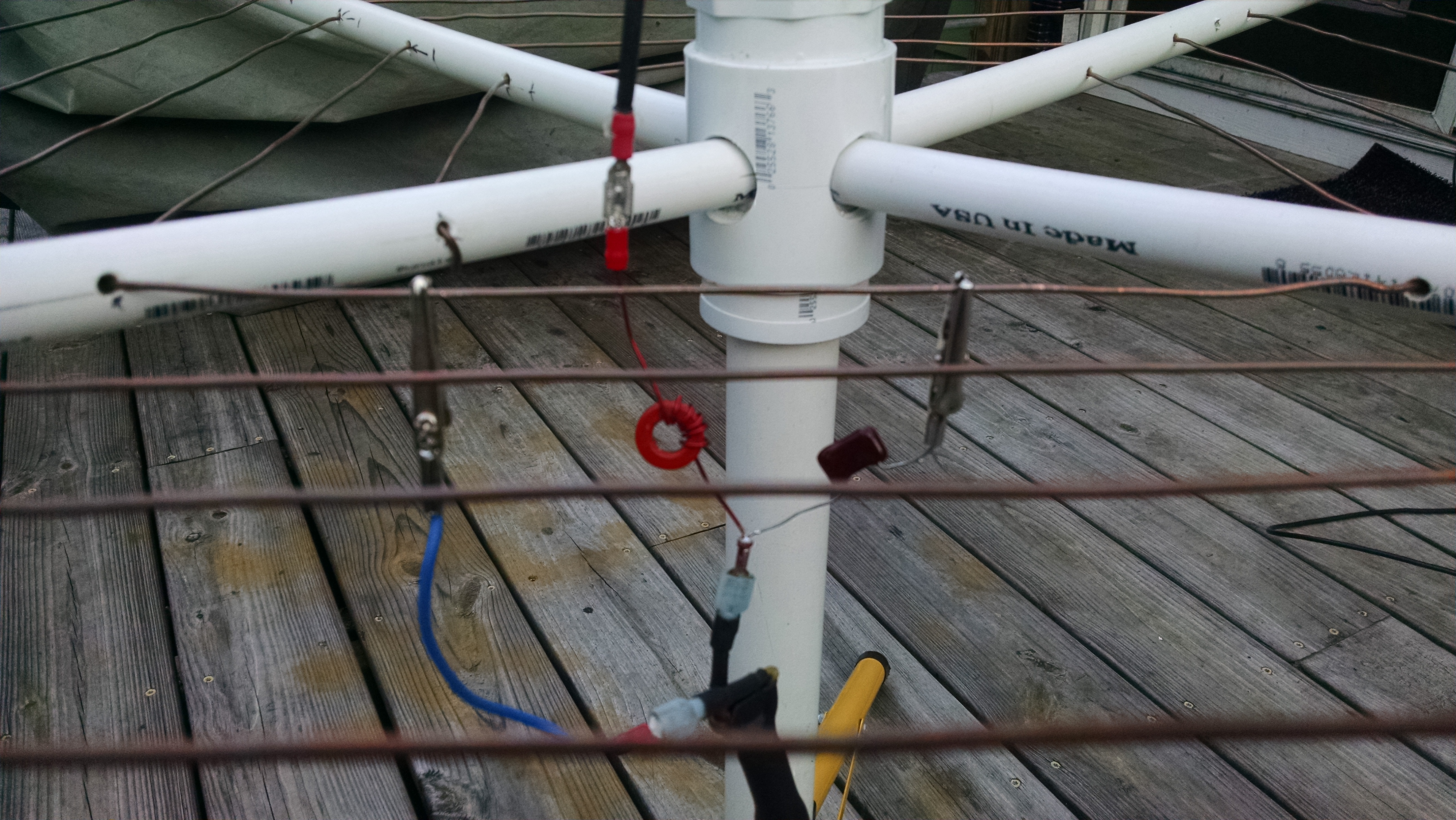
I created a simple L matching network for the antenna which works beautifully to convert the 20 ohm Z to 50 ohm at the feed point. You connect the coax ground to the spiral for resonance, then simply connect the L network ground connection to that same coax connection point. If not optimal, you can slide the L network ground connection along the spiral wire a few inches on either side of the coax ground connection to tune. The values for the L network are .5uH and 470 pF. You don’t need the network if you can tolerate the higher SWR but it feels good to see such a nice match!
L Network used to match spiral
Update: 10/05/2015
So I have done some more experiments with field strength and also done some research and found this is a topology that is a a variant of a spiral antenna. It has been coined the “spiralpole. Essentially I have created a vertical dipole where one half is the spiral element and the spiral is actually radiating significantly. This is particularly true because my spiral area is large and the number of turns is low. I had a feeling this was the case( the spiral was radiating). So the counterpoise is in fact now a radiating element. It seems to work. I plan on making a much smaller spiral coil and see what happens.

Very interesting. I’m firmly convinced that there is no free lunch with antennas, but you seem to have discovered a workable configuration. Good work.
In theory it should be possible to scale the antenna size down to work at VHF. That might allow easier experimenting with different radiator lengths and spiral dimensions to more fully understand the design.
It would also be interesting to compare your measured results with efficiency predictions from a NEC2 (or NEC4) model. Fortunately, a square spiral such as yours is easy to model in NEC2/4, but I believe there are issues (such as segment alignment) that require careful attention when dealing with closely-spaced parallel wires.
Yes no free lunch with this antenna! Feedpoint Z is low, bandwidth is narrow and it performs about the same as a vertical with 20 radials(approximately %50 loss) so to me it all seems reasonable. One concern is that the radiation pattern might be distorted. The modeling sounds like a good idea to sanity check. I think I may not have optimal design on the spiral either. I just guessed and got lucky that it was in a usable range. I will continue experimenting
Ray,
I have limited resources for an antenna and wondering if your spiral counterpoise was used with a Hamstick
antenna might prove to have some merit. the other thoughts I had was to make the counterpoise out of
circles of wire and interconnect them at the support PVC’s. If one added a 45 deg. elbow at the 2 inch
center support it would allow the counterpoise to droop and perhaps help the matching similar to what is
frequently done with VHF/UHF ground plane antennas.
73
KQ4TQ
Drooping will probably affect the radiation pattern more than Z or efficiency – just a guess. In general, the large spiral I made will out perform a small set of radials (16 or less) 1/4 wave radials on the ground. I say this based on some cursory field strength measurements, impedance and on the air performance. So if you think of the spiral as a decent performing 1/2 of a dipole – then having a full length 1/4 wave radiator for the other 1/2 dipole would be best. If I remember correctly the hamstick is fairly short – which will make your efficiency even less and and make for a pretty lo Z match. You can adjust for this with an swr meter and a movable tap for the spiral. I suspect it would work better than a two hamstick dipole, but if you can get your vertical element as long as possible – as you well know – that would be best. I made lots of contacts with my spirapole and found it to be a great choice for a small footprint vertical topology.
Ray,
I duplicated your spiral counterpoise and made a center loaded vertical to attach to it.
The center loading coil is 26.6 uH, This is about 45 to 50 turns on a ½ inch PVC. Wound with 22 AWG
from radio shack. The top whip I believe I bought at Radio shack also, and it extends to 74 inches (6
foot).
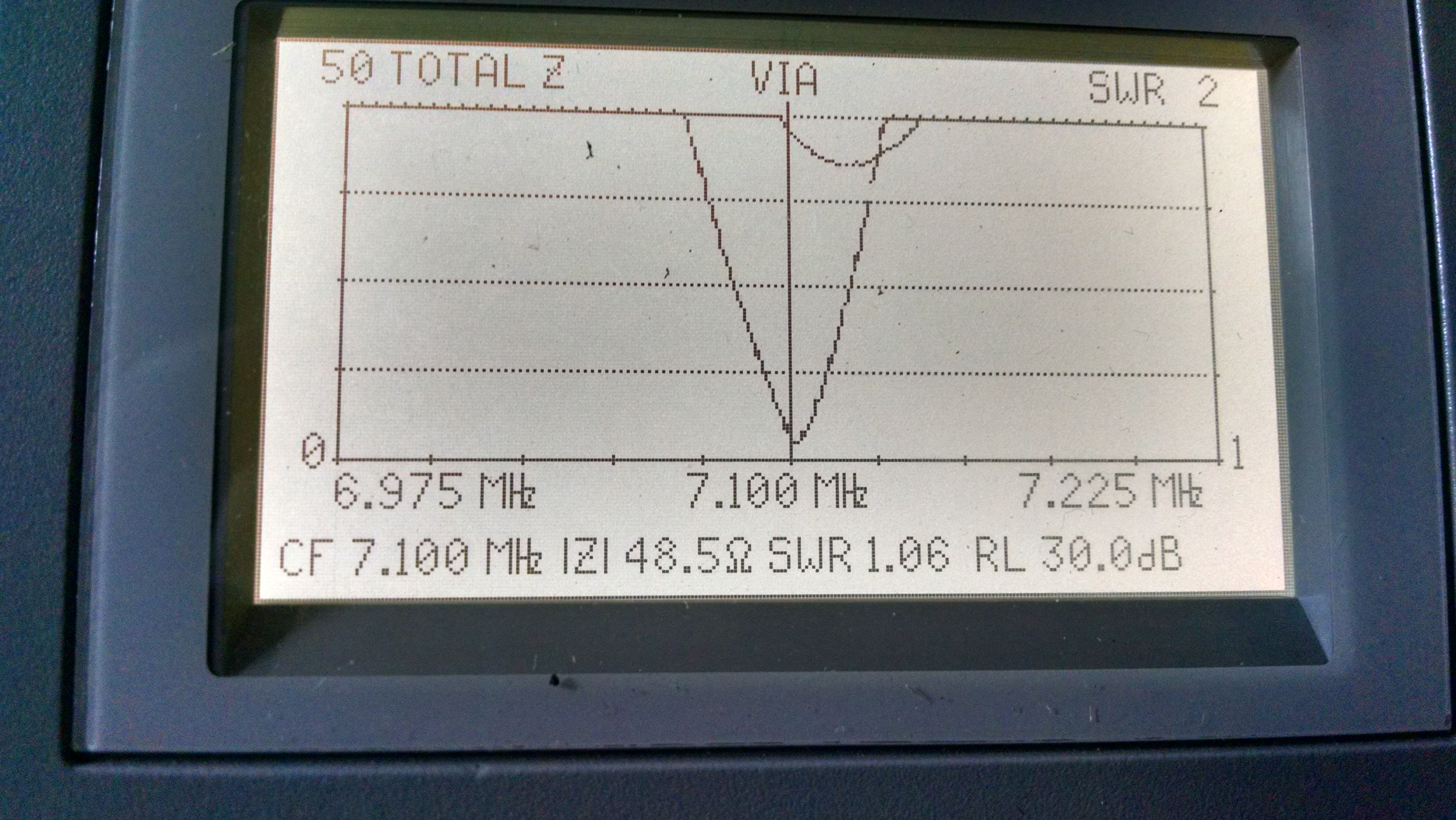
1:1 SWR = 7.0614 MHz on the MFJ meter, I would like to move this up about 80 to 90 KHz and center it
at about 7.125 MHz. Its like you mentioned that moving the tap on the spiral tunes the system.
2:1 bandwidth = 177 KHz, 6.985 to 7.162 MHz
Coax was real cold moving my hand up and down it when tuned and no change in SWR. Spiral
Counterpoise was 5.75 turns, and the coax shield connected at about the 2 ¼ turn point from the center
starting point. The coax end was split and center conductor and shield for about 9 inches was bare and
connected to the radiator and the spiral counterpoise, this give me a 9 foot tall antenna with a 3 foot
square counterpoise on 40 meters. The counterpoise was mounted 26 inches above the ground. and the
overall height from the top of the counterpoise is 109.5 inches and it occupies a 30 inch square.
This is certainly a portable antenna but is not of the backpacking type. My spiral was wound with No. 14
wire (ground stripped from 40 ft of Romex). I like your crossover and 2 inch coupling in the middle, but
I used a plug for the 2 inch coupling and drilled a 3/8 inch hole and epoxy’d a 3/8 -24 nut to the inside
this allowed me to screw in the bottom radiator.
I’ve tried to attach photos to show the set up but don’t know if they came through.
73’s
KQ4TQ
didn’t see the photos but very interested in your results..any contacts? That’s a much smaller vertical element so will be interesting to see how it does. Yes its not a backpacking antenna! It really for a small foot print fixed location like a patio, deck or small yard.