
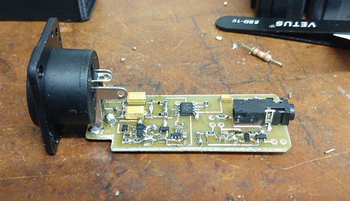
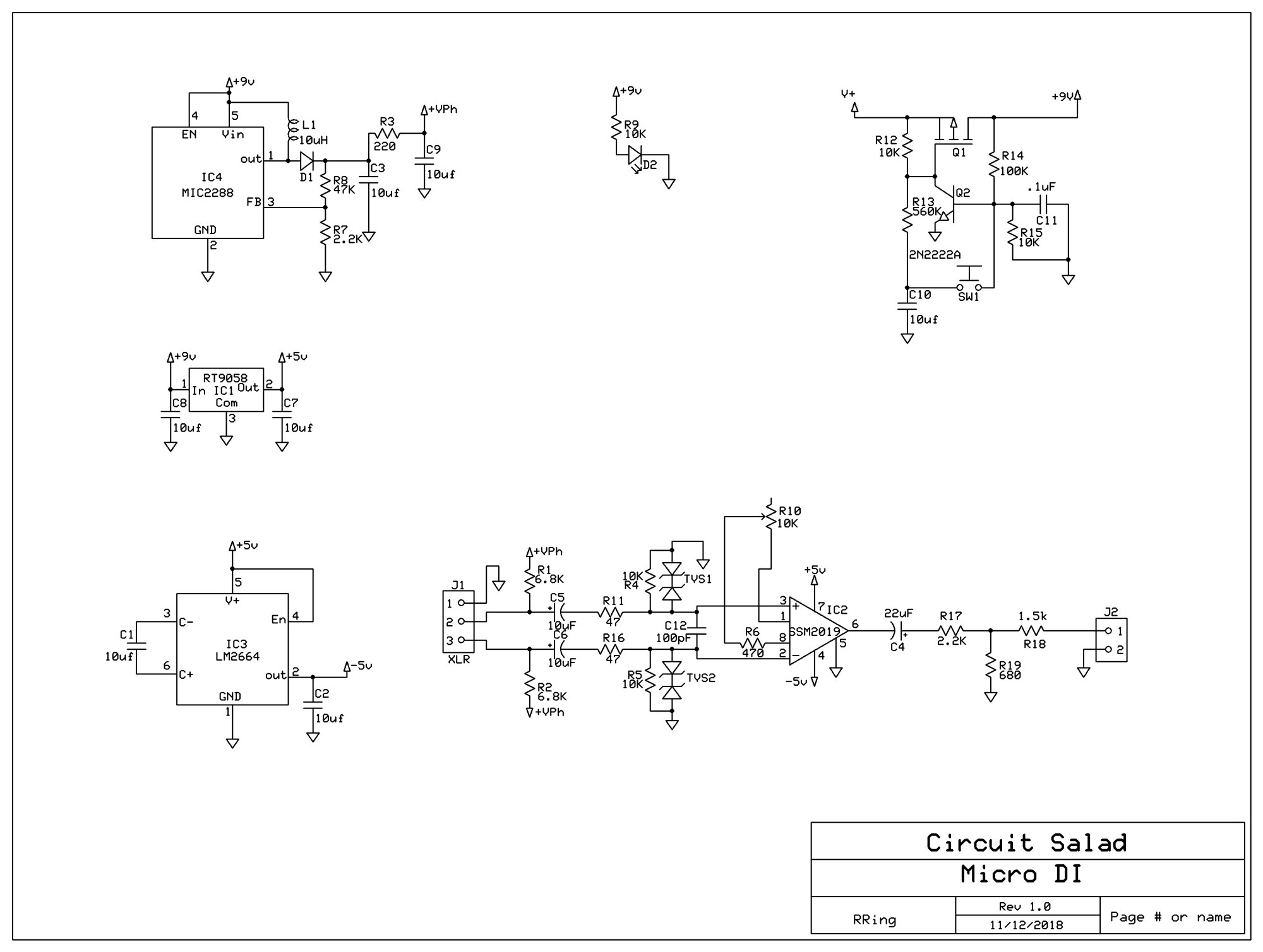
I frequently use my phone to record video for my blog and for my music projects…but I have been frequently frustrated by the limitations of the internal microphone embedded in the phone. So I created this circuit to provide a means to use a high quality Dynamic or condenser studio microphone with my phone. The circuit operates from a rechargeable 9 volt battery and plugs into the standard 1/8 inch four ring audio connector. It provides phantom power at 28 volts…which works fine …you typically don’t need 48 volts It utilizes a SSM2019 balanced microphone preamp IC, operating from a dual polarity charge pump power circuit at +-5V. At the output you need to provide a 2.2k resistive signature such that the pone can detect the microphone connection. The circuit also employs my simple momentary latching switch circuit which I often use and is described here at circuitsalad. Everything about the circuit is straightforward but the phantom power over voltage protection circuitry merits discussion. Basically, the isolation capacitors C5 and C6 are slowly charged up by the phantom supply but depending on what is plugged and unplugged can be be discharged very rapidly into the preamp input circuitry. This will be destructive and requires circuitry to shunt this energy to ground and dissipate it. This is accomplished by means of TVS1 and TVS2…which are prepackaged back to back zener diode. However the issue arises that simply using large zeners or transorbs is not a good idea because they have large reverse bias junction capacitance…which creates distortion as it modulates. To prevent this, I chose a very tiny 9 volt transorb. The one I chose (DF2B6.8ACT.L3F) has only a few pF of capacitance and is very small(402) surface mount package. The device works great but can only sink 1 amp peak. This further requires series resistors R11 and R16 to help limit the surge current to less than 1 amp at 28 volt. R1, R2, R4, and R5 must all be precisely matched in order to maintain circuit balance. R4 and R5 are required to provide a absolute ground reference such that the output does not float to some common mode DC value above 0 volts. The gain of the preamp is -6dB -20dB and is adjustable by means of R10. The reason for the negative gain is the use of an attenuation network that also provides the 2.2K resistive signature for microphone detection. The attenuation is required because of the inherent gain of the phone circuitry, which is easily overloaded.
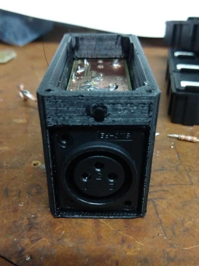
As seen in the pictures below, the circuit board fits in a compact 3D printed enclosure. The battery sits above the circuit board and is enclosed by a a top cover. I use a rechargeable 9 volt because the device draws about 30mA in total.t I included a 2.5mm circular power plug as a charging jack such that the battery can be charged without removal from a generic 9 volt battery charger.
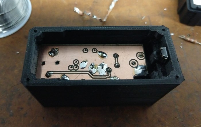
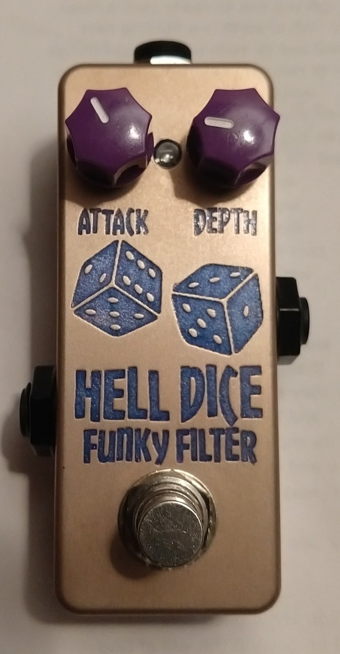
Picture of home etched Circuit Board:
Circuit Board mounted in 3D printed Case:
Link to Demo:
