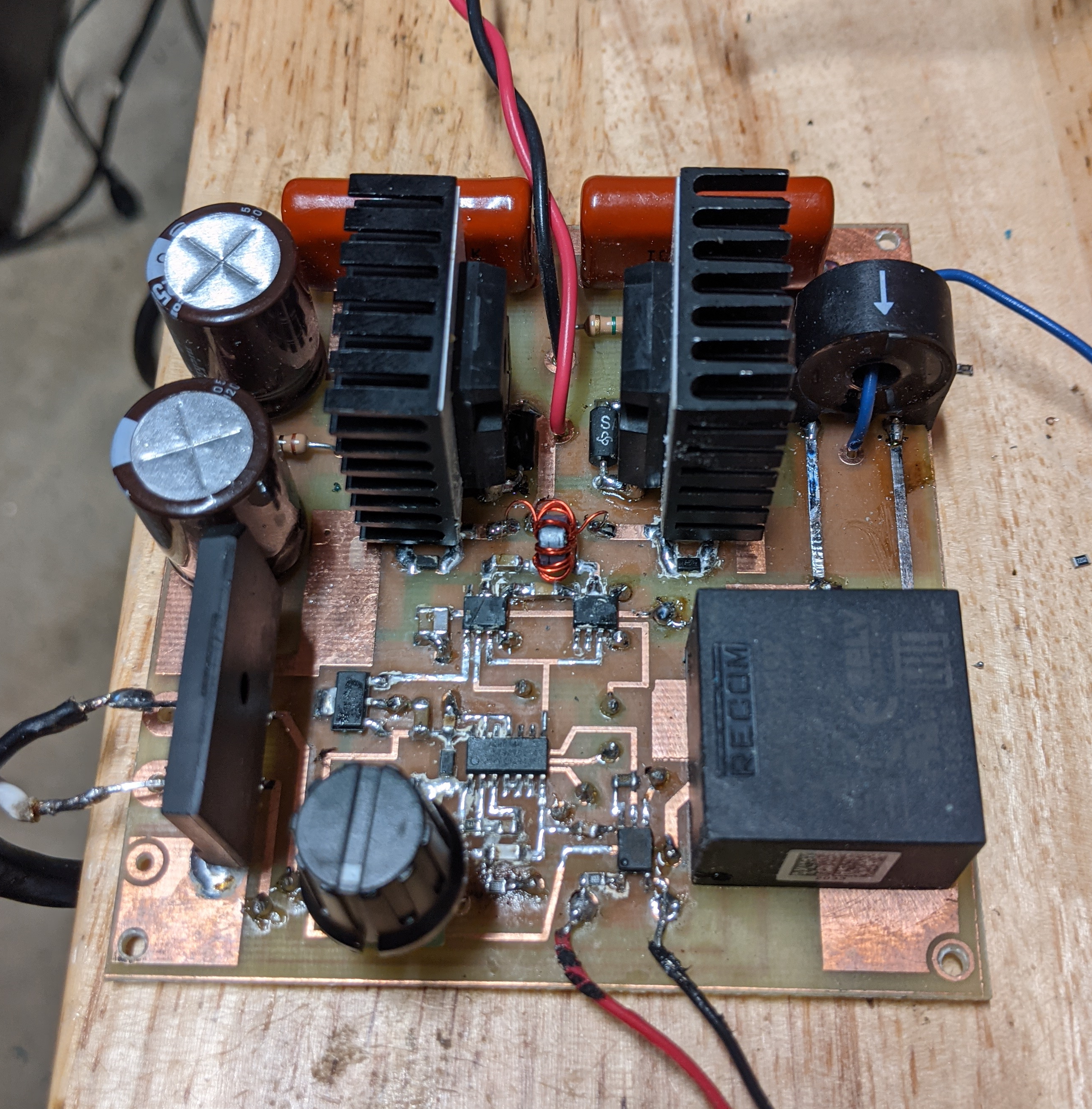
Lately, I have been experimenting with solid state Tesla Coil design ideas and after many destroyed mosfets, I have developed a reliable and efficient conventional solid state half bridge Tesla Coil driver. The topology is a basic half bridge so the primary is not resonant. This choice was made so I could operate it in continuous mode when desired. It is designed to operate with 120 VAC. The circuit is self exciting, utilizing current feedback from the secondary by means of a small 200:1 coilcraft current sensing transformer. The driver is efficient requiring minimal heat sinking of the mosfet switches. As such, the driver can be run for long intervals. The limitation on run time is constrained by the coils(secondary and primary ) and the electrolytic power supply capacitors heating up. I can generate 11 inch streamers on my 5″ diameter x 7″ tall secondary with a 6″ toroid terminal. I can just change out the different secondary and primary combinations I want to test, as the driver will easily operate from 100Khz to over 1 MHz. Depending on the frequency, you may need to change one resistor. The driver board is only 3.6″x 3.6″ and including simple stick on heatsinks for the mosfets.
Features that improve efficiency and reduce mosfet heating:
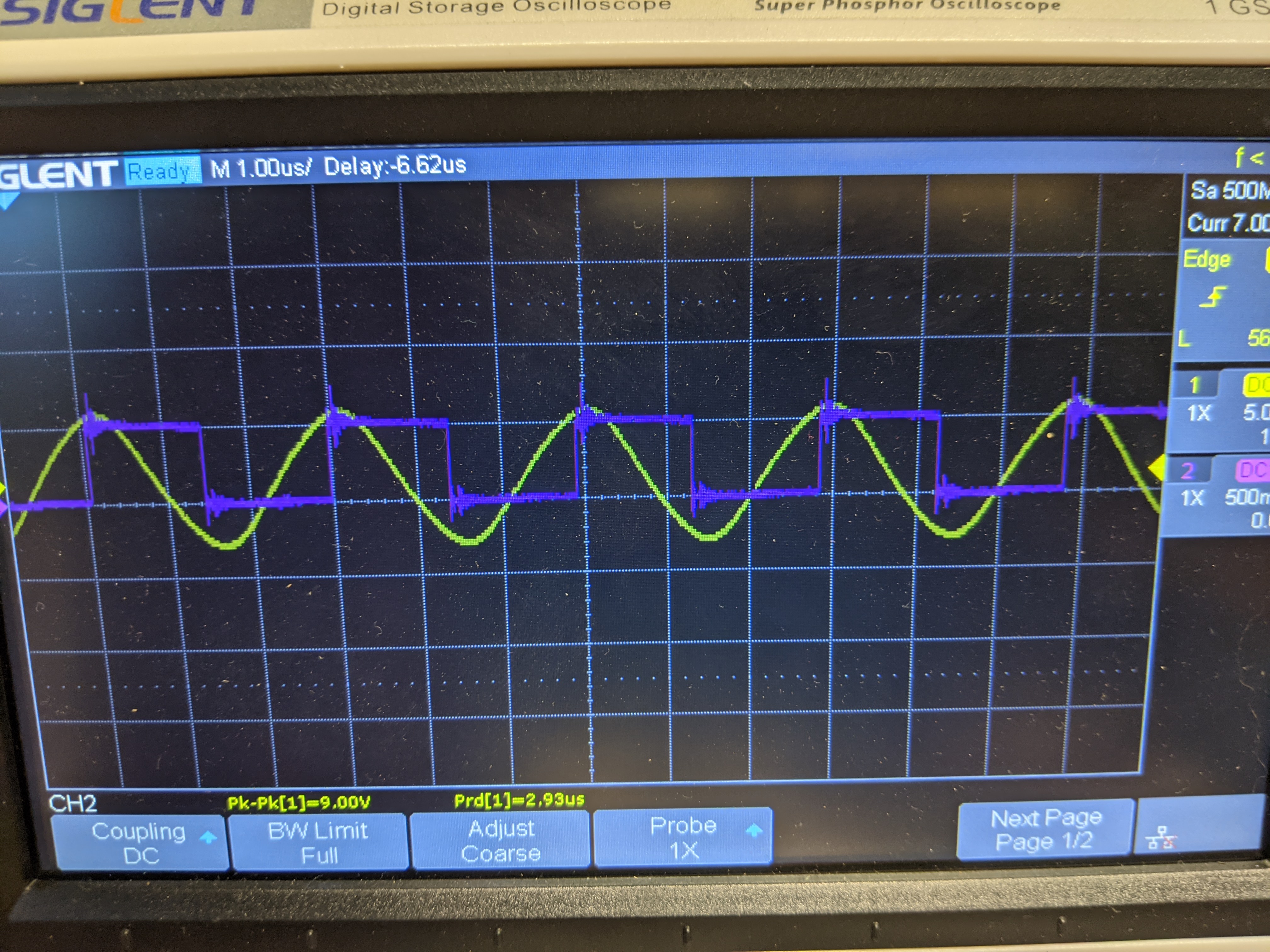
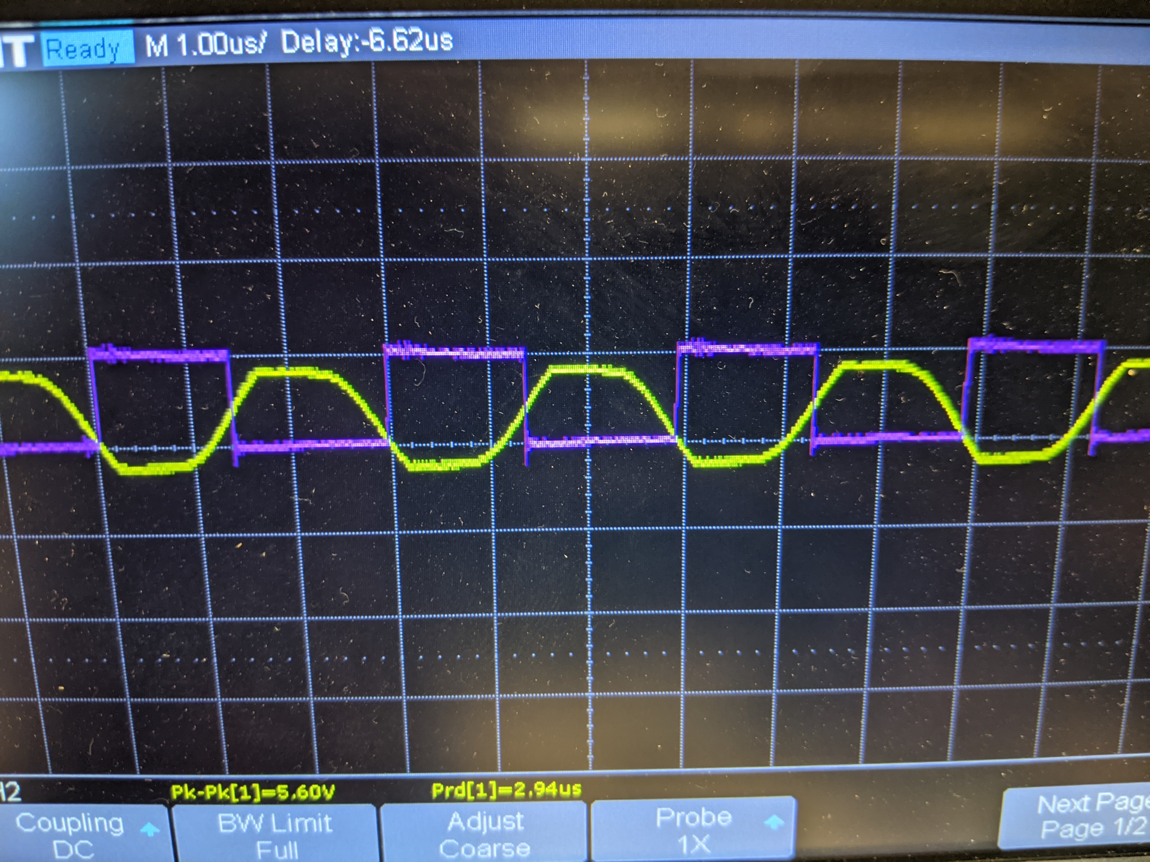
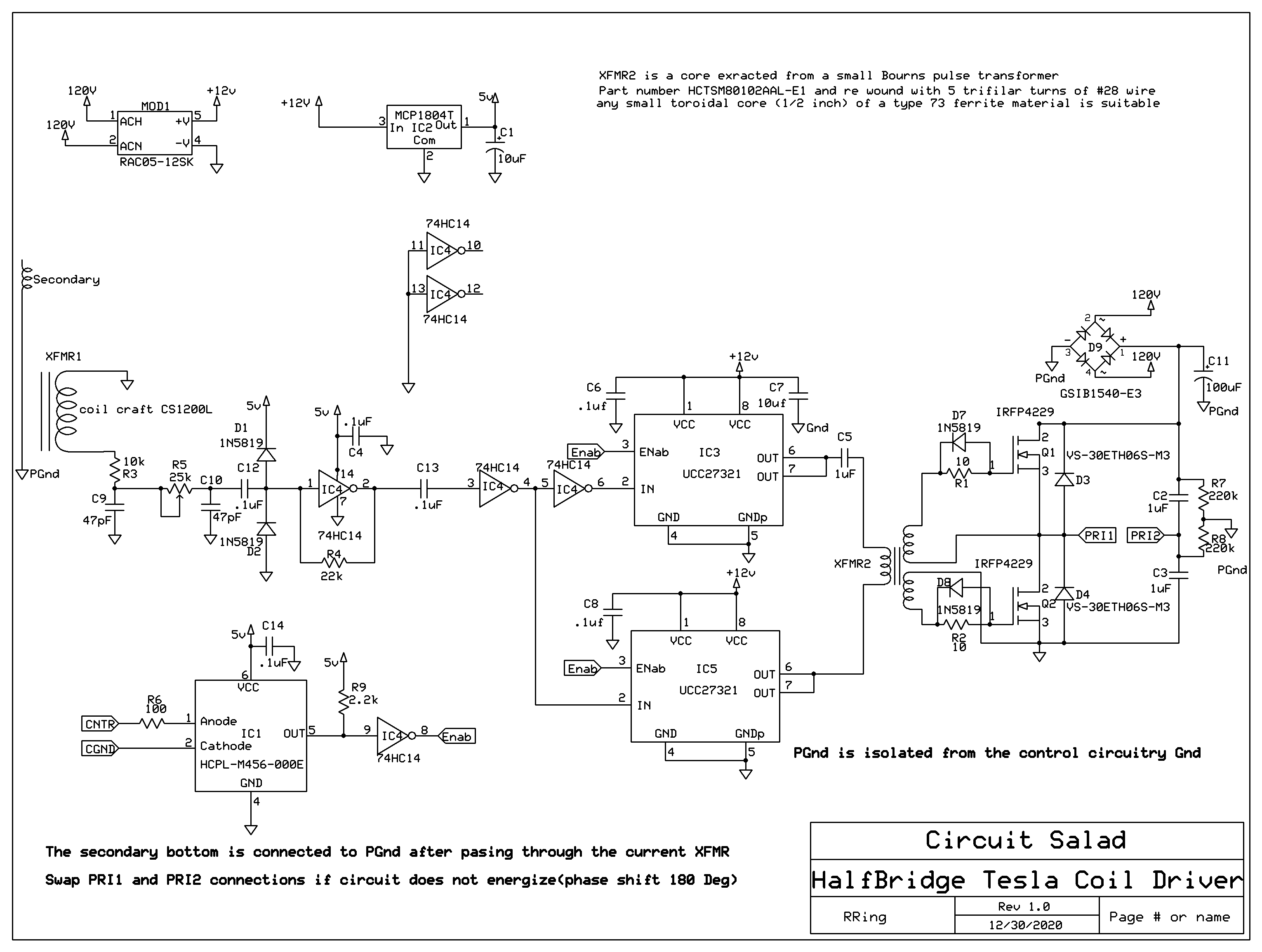
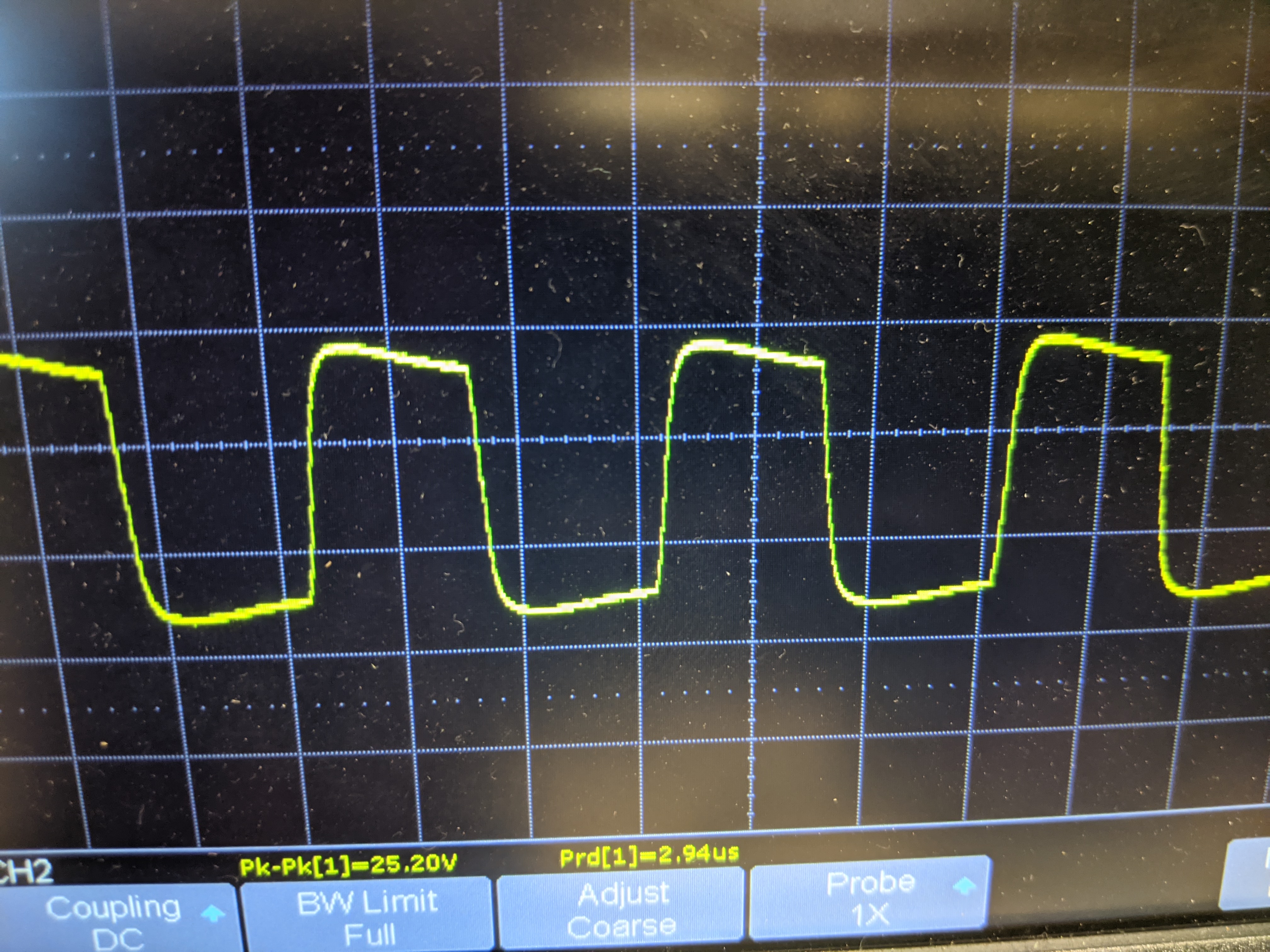
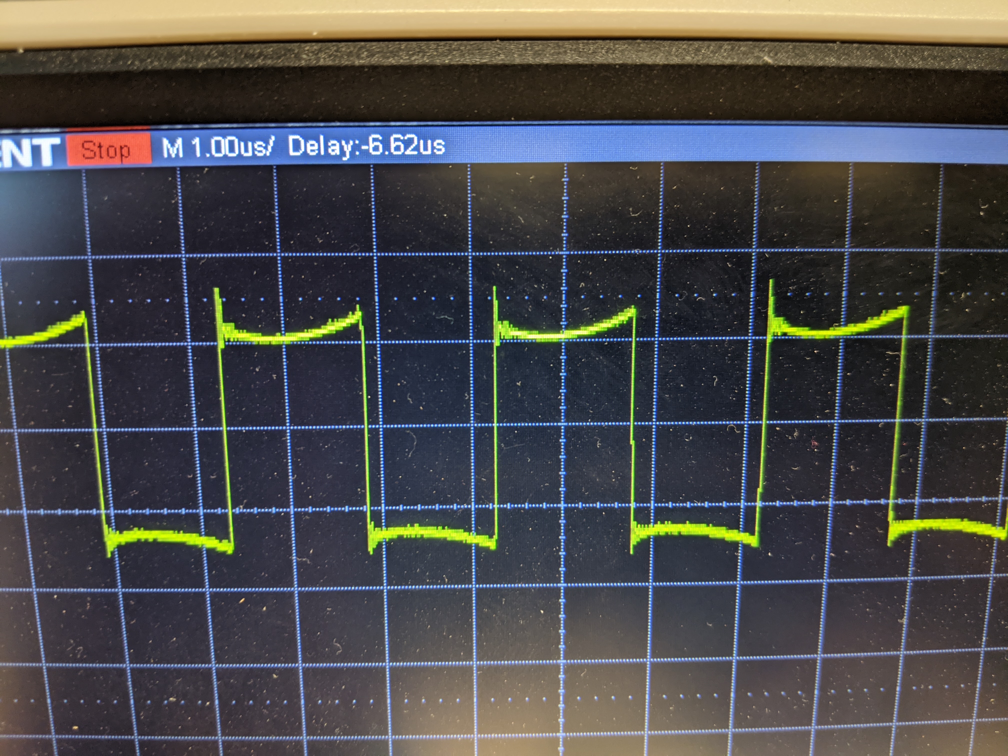
Properly designed gate drive: I used an appropriately sized and correct ferrite material xfmr core for the drive transformer. The core I used is very small (.3 inches) and was cannibalized from a small pulse xformer obtained from Mouser(photo below). There were no cheap small cores available on Mouser so i just found a small pulse isolation transformer that was inexpensive and I could get the core from. If you prefer, you can purchase stand alone core. Type 73 material is a good choice and a core no bigger than a .5 inch will be fine for this circuit. I cannibalized the core out of the housing and re-wound it with a trifilar 28 gauge winding of 5 turns. I also placed schottky diodes across the 10 ohm gate resistor providing for slightly faster off time than on time, This ensures minimal shoot through(both mosfets on at the same time). The drive is clean with no ringing and fast rise and fall times(pictures below). This reduces switching losses.
Choice of mosfet: I wanted to select a low cost and high performance mosfet for the circuit. There are two I found that work well. The basic criteria are : > 250V breakdown rating @ > 20 amp current capacity. Low output capacitance, gate capacitance and on resistance were also important. The IRFP4229 is the ideal candidate. It has a breakdown of 250V. It can handle 40 amps of current, and has total switch delay of of 100ns(very fast). The on resistance is .04 ohm; so IR losses are low. A similar device, only slightly slower and with a slightly greater on resistance is the STW46NF30. Both were evaluated and worked well. The cost of both of these mosfets is around $3 each.
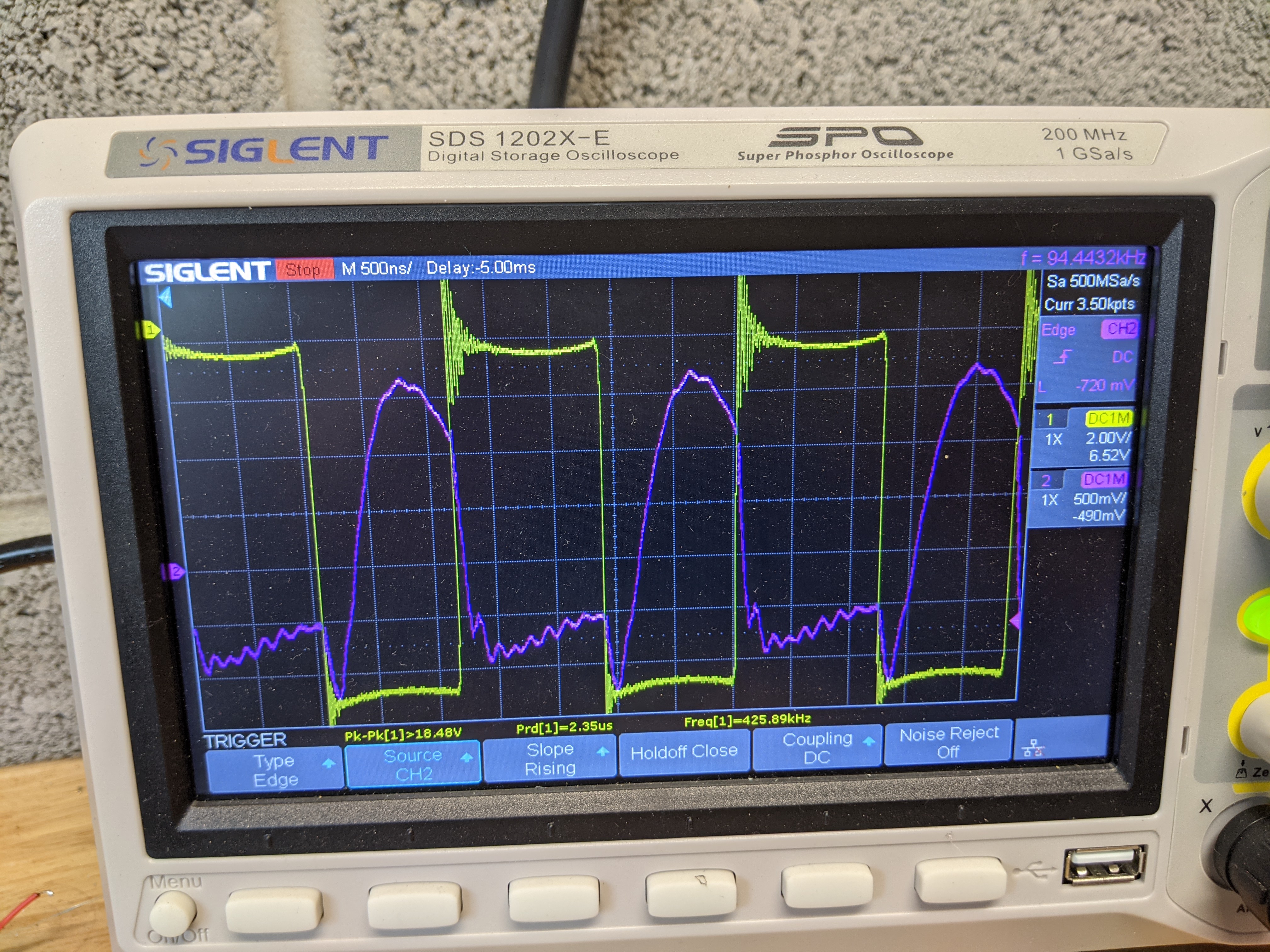
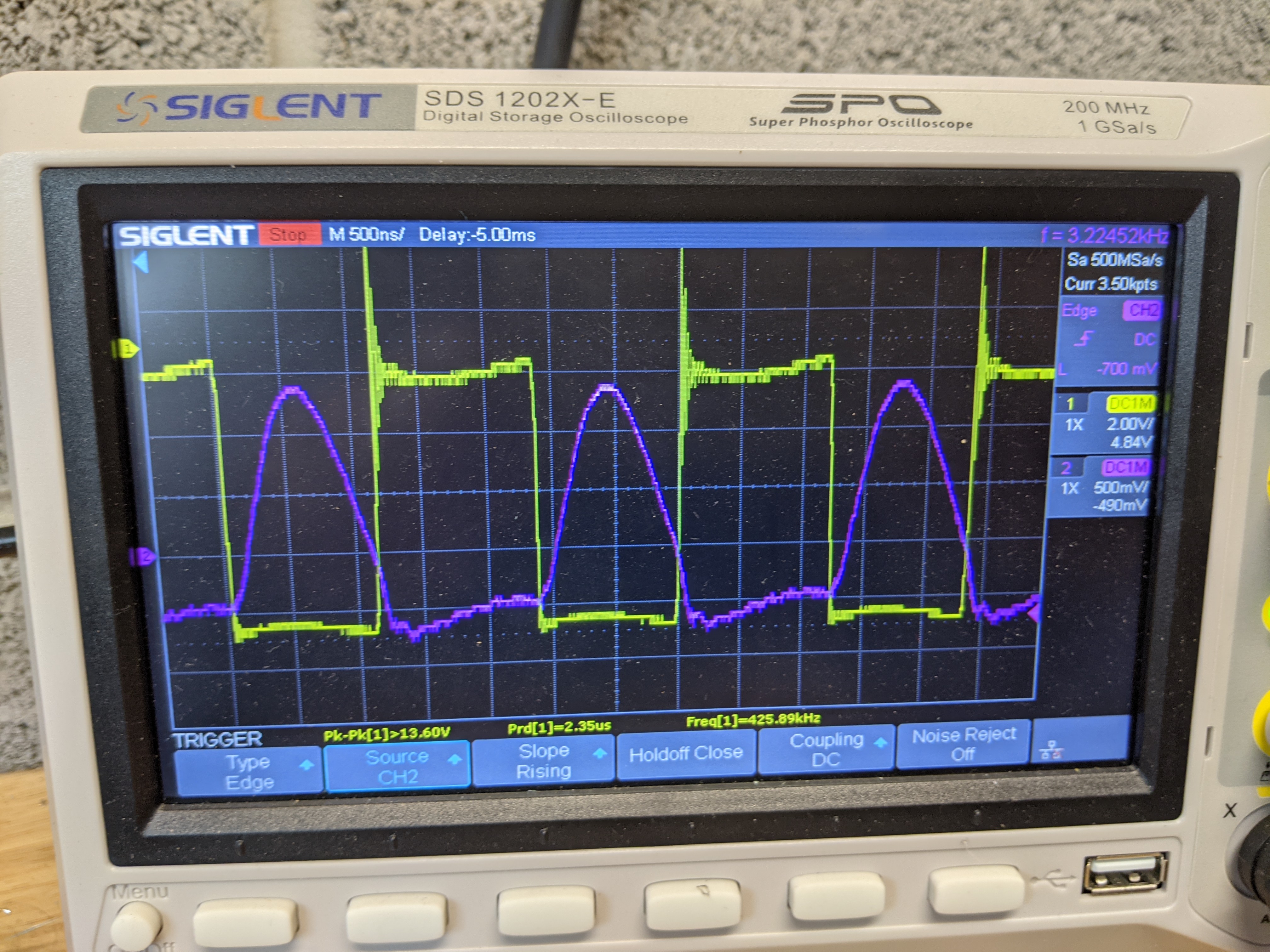
Adjustable phase shift control in feedback loop: A substantial improvement in output and efficiency was obtained by placing a simple low pass RC phase shift network in series with the secondary feedback path. It was observed that when my test coil was driven from an external source, the input drive was approximately 90 deg out of phase with the secondary output. This was the case when the coil was tuned for maximum output. This amount of phase shift will not support oscillation properly. Forcing the coil to self excite will not produce optimal output unless some sort of phase shifting is employed. The notion that a self excited tesla coil will inherently tune itself to best performance is incorrect. Adjusting the input /output the phase relationship maximizes coil output but also lets one adjust the drain voltage/current relationship such that zero crossing switching can be obtained. This is when the current and voltage across the switches do not overlap. This greatly reduces power losses across the switch. The phase shift network consists of two simple RC low pass filters in series. One with a fixed resistor and the other is a variable resistor to allow adjustment. The low Q nature of the RC filter provides optimal tuning over a wide range and is easy to adjust and is stable. The values for the filter as shown in the schematic are easy to calculate. Simply pick a resistor value(10k for example), then use the approximate value of operating frequency(+-20% is fine) to determine the capacitors required. The value of capacitance is correct when the reactance of the capacitor at the given frequency is the same as the resistor value(10k). Or chose a capacitor value such as 47pf. With this value, the reactance at 650KHz is 1/2Pi(650KHz)(47pF), which is 5212 ohms. So you could use a 4.7k resistor for one RC stage and a 10k to 50k pot for the second stage. In my example coil, the frequency is around 400KHz and so I used 10k with 47pF and a 25K Pot with a 47 pF for the second stage. The low pass characteristic of the phase shifting also has the benefit of reducing higher frequency noise and parasitics in the feedback loop. The result of this simple addition to the circuit is substantial and when you tune the variable resistor you can see the output significantly increase and decrease. You can monitor the drain voltage and current to adjust phase for optimal performance. Alternatively, I have found that you can simply adjust for longest streamer length and then add just a tiny bit more phase shift to optimize switching efficiency.