Some one asked me to share the files for my 3D printed telegraph key. So I am going to do that.
Here is a link to the STL file for the key parts.
https://www.adrive.com/public/GWBRqy/Code_key_stl
There are 3 files that print the base, key and upper bracket separately. All of the holes are included but they are undersized. Some you will drill larger and others are tapped. There is a horizontal hole in the key to run a wire back from the top key contact and the same is true for the base. I printed at 100% fill using ABS. HIPS would work well also. The magnetic damping instead of a spring works really well. The 4-40 contact screws need to be filed flat after being nipped to size.
Required Hardware:
2″ of brass 1/8″ rod (for hinge point)
2 3/8 6-32 screws (front legs)
2 1/2 6-32 screws (mounting upper bracket)
3 3/4 6-32 screws (Key adjustment and back legs)
7 6-32 nuts
2 6-32 knurled nuts
2 1″ 4-40 screws (for key contacts and holding magnets…will be trimmed)
2 4-40 nuts
misc 4-40 washers for spacing adjustment
2 .6″ diameter rare earth disc magnets with center hole
24 gauge scrap wire
Bottom View
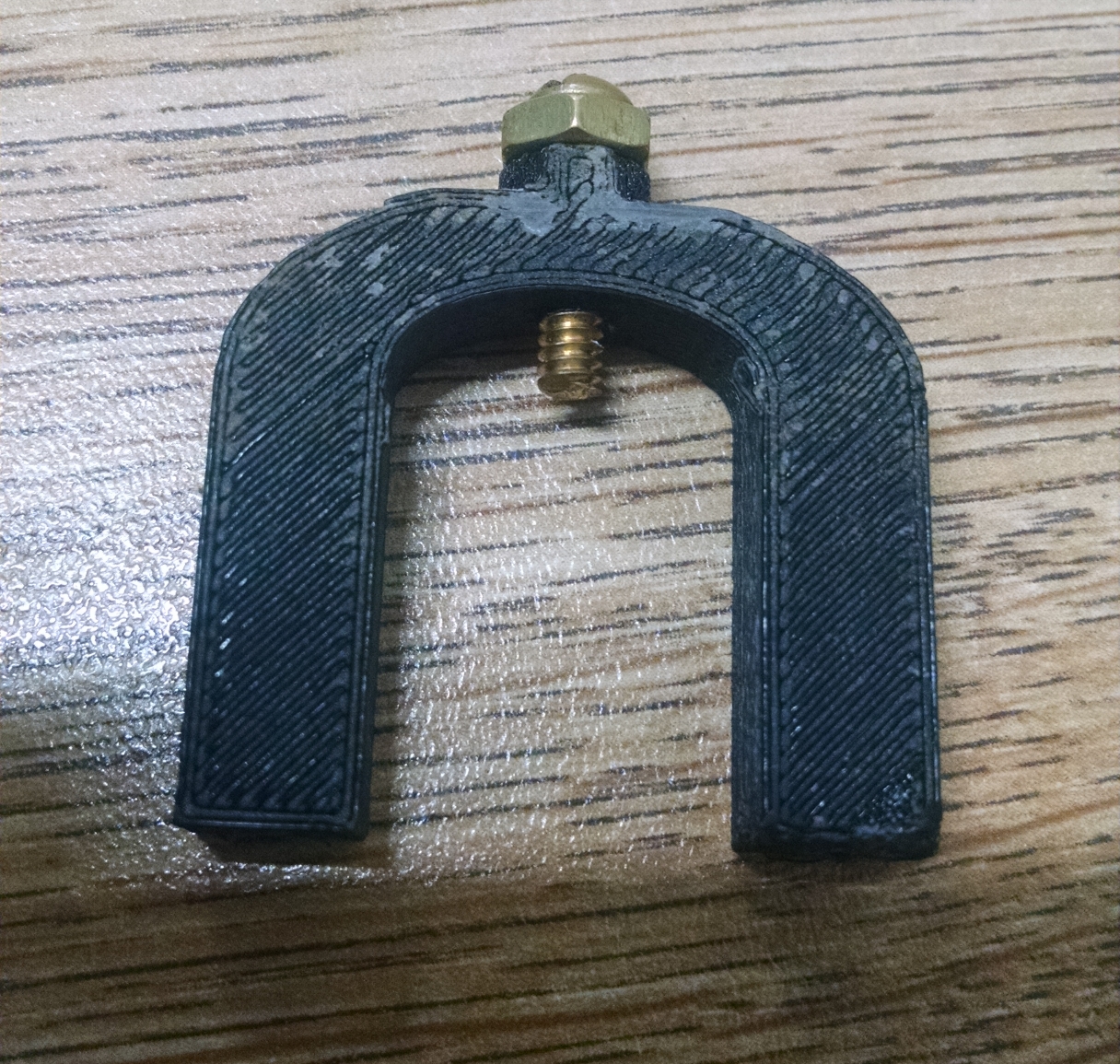
Top Bracket
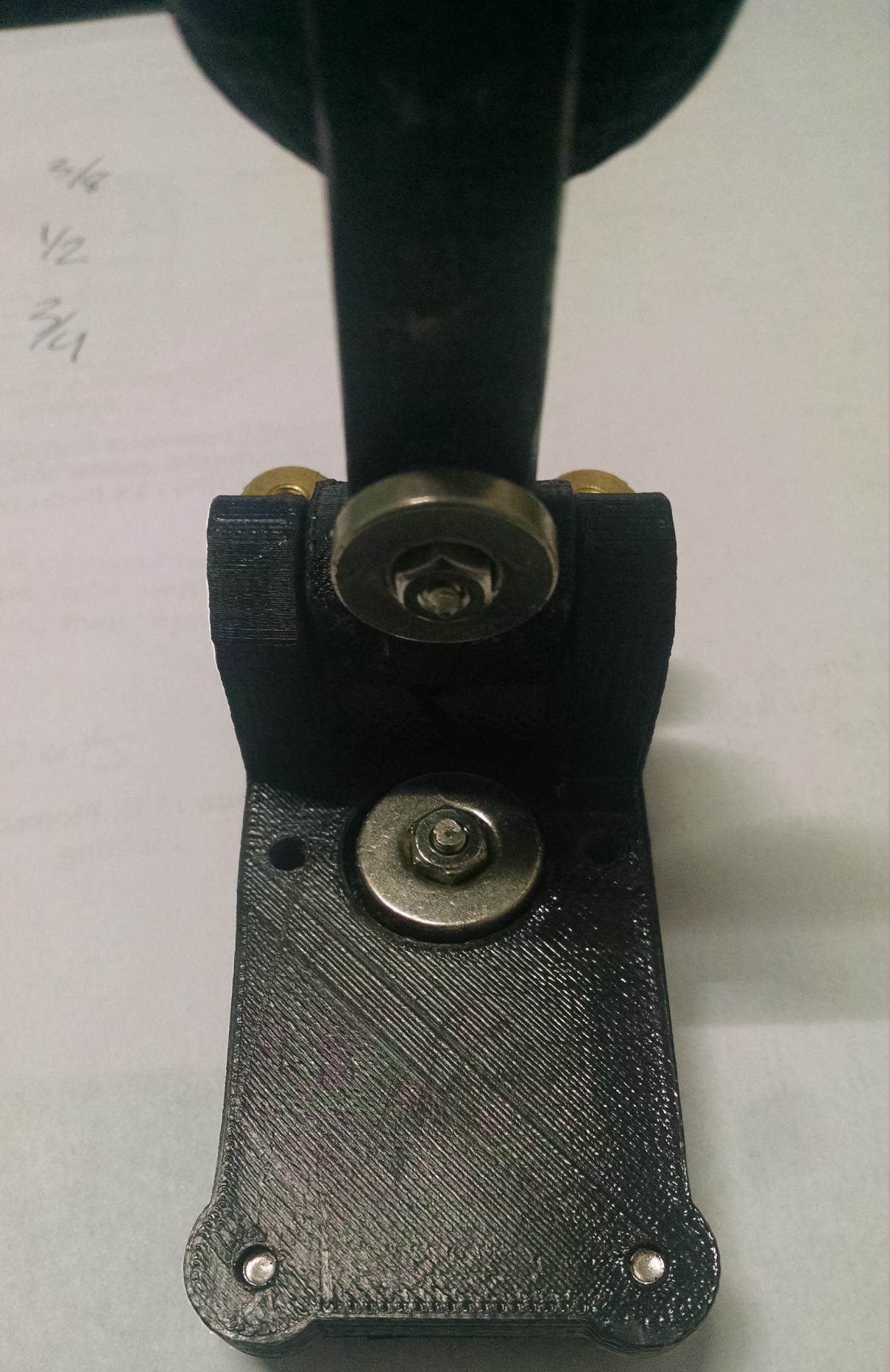
View of Magnets and Contacts
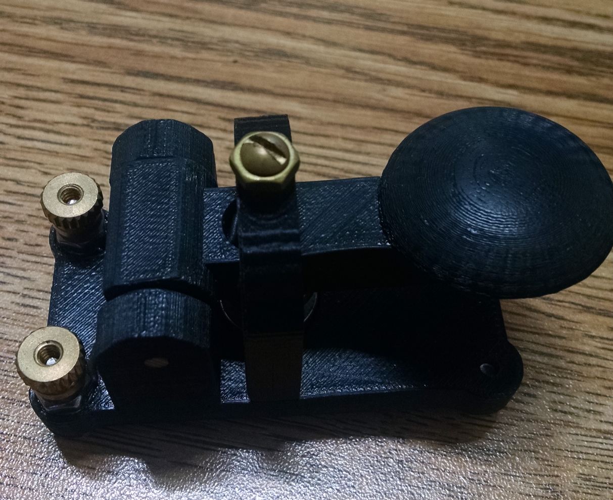
Side View
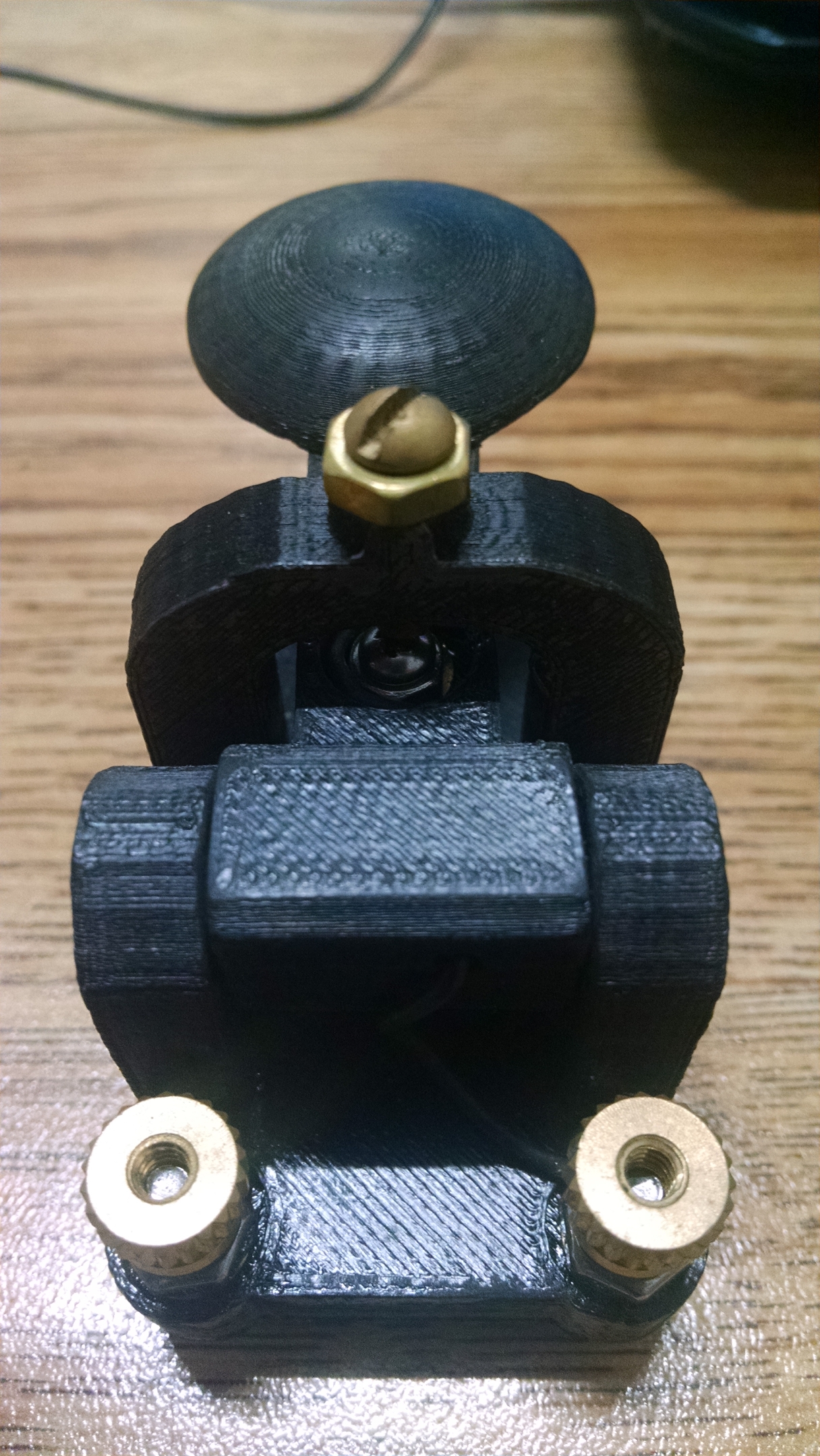
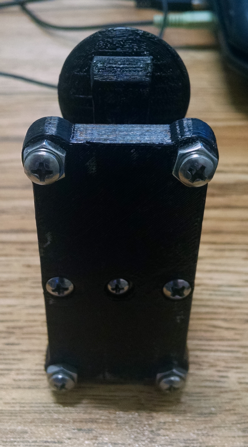
Back View