
This receiver is a simplified version of my quadrature sampling receiver. It is simplified because it does not require the phasing filter section and also does not divide the LO by 4. This simplifies the local oscillator requirements significantly. The receiver uses a 2 pole low pass filter for selectivity and a TDA7052 audio amplifier. The CS2000 is a SPI controlled clock generator and is used for frequency generation and tuning, but any VFO, VXO or any other stable frequency source will work. In this case, one of the extra inverter stages could be used as a linear amplifier to boost up the oscillator output if required(need a good squarewave). If this is done, the micro-controller can be eliminated. The input RF amplifier can also be eliminated if you are using an approximately 50 ohm resonant antenna. In this case the antenna would connect through C13 to pin 9 of IC5. If you do this – pin 9 must also be biased to 1/2 supply. This can be done with a couple of 4.7k resistors connected in series from V+ to Gnd. The center junction point will go to pin 9.
This receiver can receive AM but must be at zero beat(exactly tuned). The CS2000 has a resolution of 1Hz or so and is very stable – so the receiver work pretty well for AM. Unlike the phasing receiver this circuit cannot eliminate one of the side bands, but to be honest its not worth effort unless you want contest grade ham receiver performance.
In the video you can see I break out the power switch, audio gain, tuning encoder and display to a daughter board.
I designed the display to have very low spurious noise. The info on this is here:
https://circuitsalad.com/2014/07/31/very-low-power-3-digit-lcd-display-with-serial-control/
More info about how this circuit works can be found in this post, which is the quadrature version of this receiver.
https://circuitsalad.com/2013/12/30/my-phasing-receiver-is-a-success/
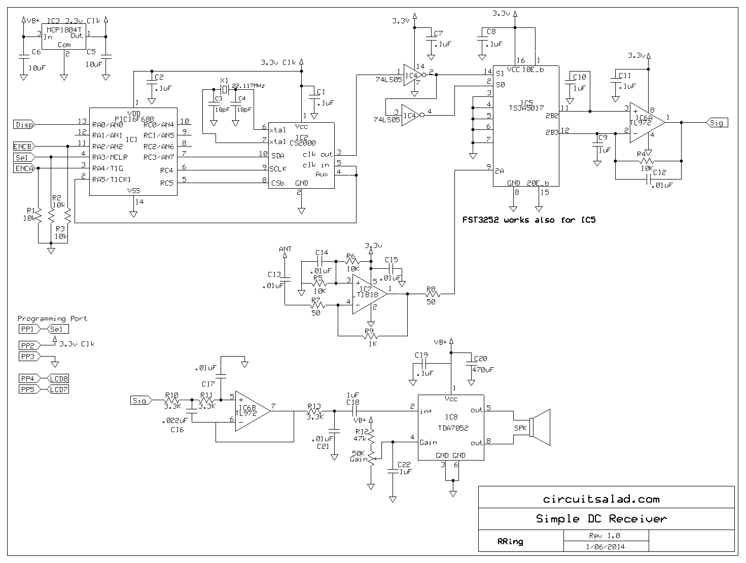
Schematic:
Demo Video:
zip file of code: Filedropper is full of dumb ads but look for the “Download This File” button in middle of screen

Just curious…In this latest design, the CS2000-CP’s CLK-IN is linked to the MUX pin, and these are connected back to the PIC. In the earlier design, this wasn’t done. In the absence (yet) of any demo code, what’s the reason for this change? (I looked at the datasheet, but the answer wasn’t immediately obvious to me, sorry!)
Also, can any (sensible) crystal frequency be used on the CS2000? For example, if I don’t have a 22.179MHz, can I use, say, a 20 or 24MHz crystal, which I happen to have in my junkbox of parts, assuming I recalculate the various values to send to the CS2000?
Thanks!
yes you can use any crystal…it just changes the math for frequency calculation. You do get some spurious artifacts(3 or 4 )over the range of tuning. I chose my crystal to keep these out of bands of interest – having said that just about anything will work fine.Yes in the first design ..I did not provide a proper reference clk (you need to feed the clk back to the aux pin) for the mode I was using. It still worked, but I noticed new version tunes better at the very fine increments.The connection goes back to the PIC because I use the CS2000 output clk as the clk for the PIC. I will post a link for the code this week. I use mikroelctronica MikroC as my compiler. The radio is a lot of fun when I am in my lab after dinner, I listen to radio Cairo while I work
I added a link to my code- which is designed to work with my LCD driver(on circuitsalad also).
Thanks, that makes it clear.
I’ll take a closer look at the code that you’ve uploaded as well. This will help me to interpret the datasheet which, for me at least, is hardly a model of clarity. It reminds me of the early Intel datasheets, where the most critical and vital detail was invariably placed in a minor footnote, say on page 17 of a 51 page datasheet. Every. Single. Time.
I also am planning to use an ATtiny and an I2C driven serial LCD so that will mean a few minor changes to the code, but nothing too significant.
Thanks again.
My code is not the best commented but the basic spi write routines and command codes required to make the thing work dead on and should help you get started. The data sheet is not good at giving application examples and how the configuration would relate so its a little painful… that’s why I did not get the reference clk termination correct in the first version!
Your choice of CS2000 is intriguing indeed due to its low power (I am also thinking of building a low power DSP RX sometimes). It would be interesting to measure the phase noise of this synth though.
There is one thing I miss here. DC receivers need some RF selectivity to avoid conversion on harmonics of the LO. You basically need either a bank of fixed octave filters or something tunable in the RF front end.
have not done a formal phase noise evaluation it’s a frac N and has some harmonic spurs(show up as birdies at certain frequencies)relating to the fraction divide and subsequent filtering. On a spectrum analyzer …it looks good(for what its worth). The data sheet describes very low levels of jitter. The device is is intended as a clock source for 24bit high sample rate audio dsp…etc so I suspect it can be made to give excellent results for receiver application.
With regard to selectivity, the differential nature of the sampling switching eliminates some of the harmonic products you are describing. With no front end selectivity you do get some harmonic mixing with the second harmonic. I use a tuned hi Q receiving loop as an antenna to mitigate this. However the shortwave bands are not that crowded these days so I just don’t run into much spurious mixing signals.
To be clear..yes RF front end selectivity is appropriate for a high performance receiver of this type and probably a dsp “square law detector” for AM. As it is currently you have to zero beat any AM signal.
This was intended just a fun sort of radio to see what I could get away with.
A hi-Q loop explains it ! I was thinking of a tiny portable with a telescopic or even a phone wire antenna in which case some RF filtering is required.
Also It looks like Cirrus now has a family of devices based on CS2000. CS2200 is a bit cheaper and seems suitable.
I have a setup to measure the phase noise of an oscillator at a fixed frequency of 10MHz (crystal reference) with sensitivity on the order of -140dB/Hz @ 1kHz. If I get time to play with CS2x00 chips I’ll report the result.
I use a straight wire also still works okay. The loop mainly helps with nulling electrical noise in the city. The phase noise measurement would good to get…so definitely keep me posted. One of those cirrus parts is a one time programmable device so make sure that the 2200 is not a one time device.
the cirrus chip is easier to implement than a DDS and I am lazy so that’s why I used it!