
I decided to try using a small wide band E field type antenna with my newest receiver design…the Mini SDR and the results have been gratifying. There many useful articles describing this type of antenna; so I won’t go into much detail about how it works. More or less it functions as a capacitive E field probe and therefore is very sensitive to EMI. However, if placed outside away from house wiring and provided with a modest local ground reference..the antenna is a good performer. The classic circuit uses a JFET source follower and a BJT follower stage to provide impedance transformation of the Hi Z capacitive terminal to a 50 ohm Z drive for transmission line. This circuit works fine but has some drawback, namely requiring 65mA of current and having a somewhat large input capacitance, which reduces performance with frequency. I decided to use a wide bandwidth op amp to simplify the circuit, reduce current, and provide a little voltage gain. The op amp I chose was one I have used before for RF amplification..the LT1818. When choosing an op amp for such an application..there are a few important criteria to focus on:
1. current noise: Unlike low impedance topologies where voltage noise and resistor thermal noise will dominate, having a Hi Z input will make the current noise the dominant source of amplifier noise.
2. Bandwidth: you need a wide bandwidth on the order of hundreds of MHz or more to provide the required frequency response up to 30Mhz. This is especially true for voltage feedback op amps, where the phase shift compensation rapidly reduces performance over frequency.
3. Slew rate: You want the largest slew rate you can get to reduce distortion and IMD products.
4. Input bias current/ input Z/ input capacitance: You need low input capacitance so as to not to create a lossy divider with the antenna terminal. You want low input bias current and high input Z to not load down the terminal. If the input bias current is too high , then you need a low value bias resistor which loads the terminal.
5. Low output impedance: To drive 50 ohm Z and minimize distortion.
The LT1818 has excellent specs with regard to all of these criteria. It can operate on 3v-12v and requires only 9mA of current to operate. The Amplifier will operate from VLF to beyond 30Mhz with no change in performance.
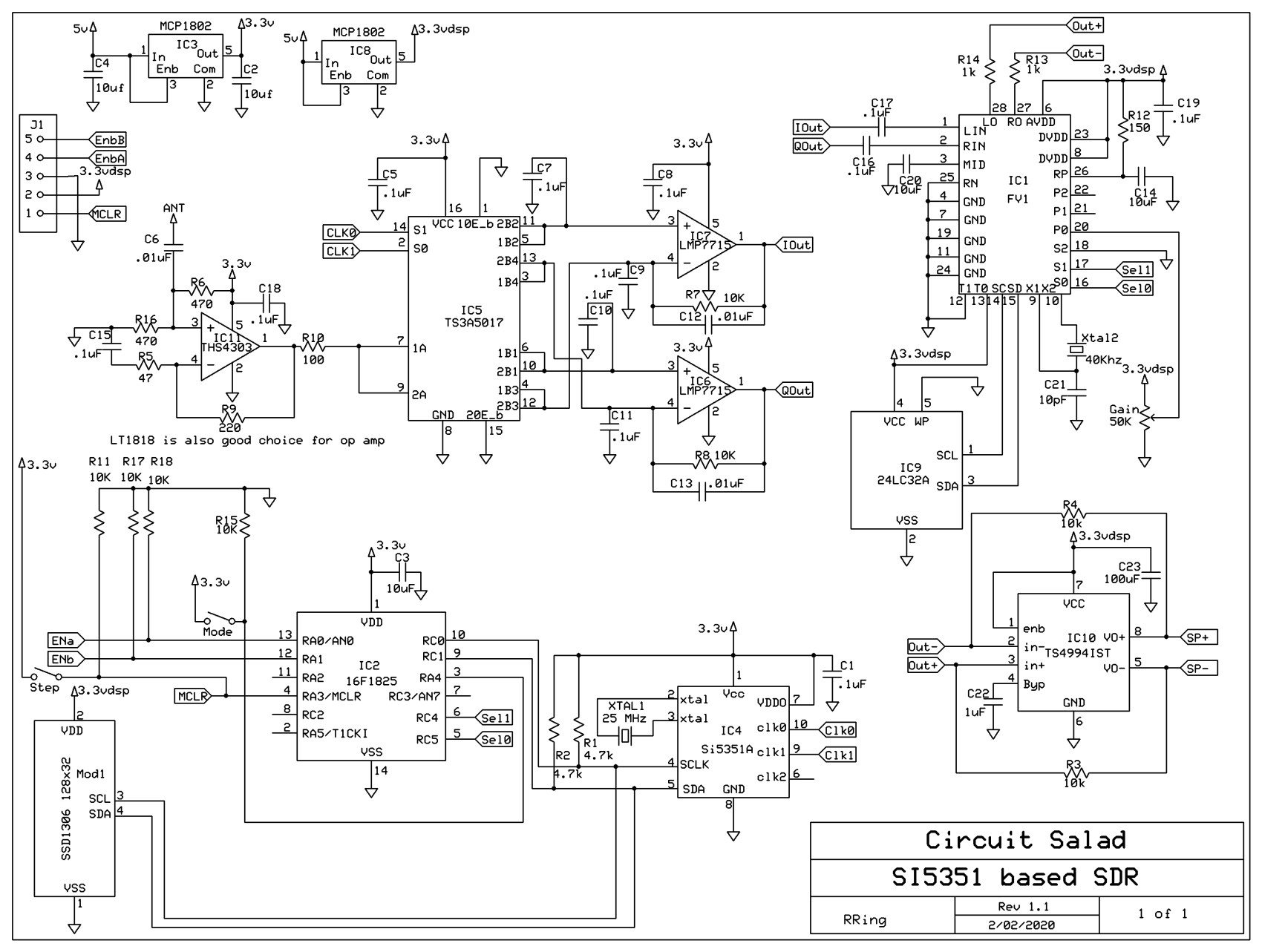
Schematic:

The antenna is powered via a power splitter connected between the receiver and antenna. This is the purpose of L1 to isolate the DC power from the RF output from the antenna.
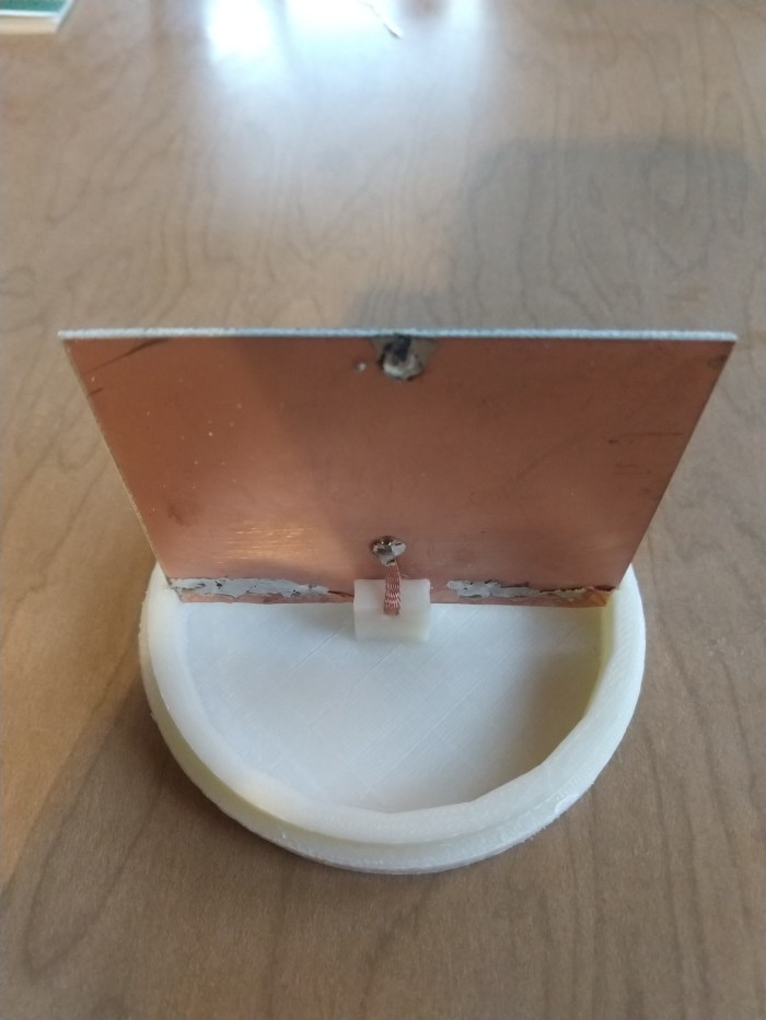
I 3D printed antenna capsule from HIPS, which is a low RF loss material and used a 3″ square of PC board to create the capacitive antenna terminal. The printing was done at 50% density so it’s a very light, low dielectric loss enclosure.
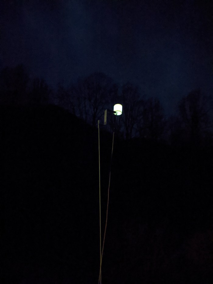
Installed Antenna(with LED illumination)
Antenna Element

Complete 4″ x 1-1/2 inch antenna

Amplifier Circuit

Antenna Terminal
Efield Antenna Demo:
