
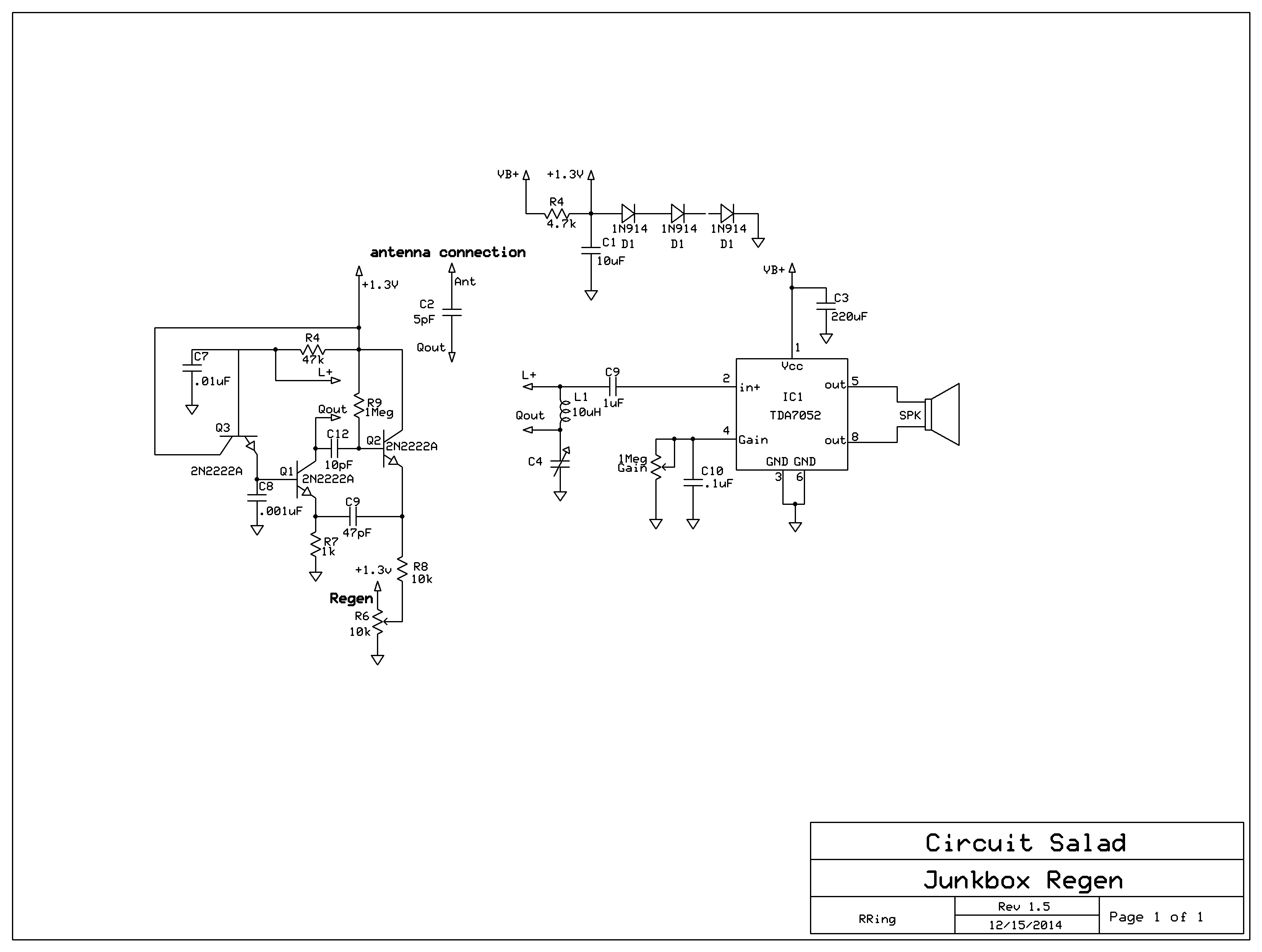
In this version, I removed the darlington detector and added a emitter follower(Q3) to bias Q1 and act as a reflex detector. With this arrangement the circuit works best with a supply voltage from one to two volts or so. I used three diode drops in series to achieve this. You could also use a LED. It has extremely smooth regeneration. The selectivity is excellent.
Again I got it to work with a wide range of values, so it should be easy to reproduce. I hope someone builds this and gives me their opinion on performance.
Schematic (revised 07/01/2015)

This looks great! I have a 1.2-volt AF amplifier that I’m using in my current regen (http://theradioboard.com/rb/viewtopic.php?p=54134#p54134), which might be interesting to try to hook up to the above circuit for a 1.2-volt receiver.
I must admit to being rather baffled by exactly how Q3 is supposed to work in this circuit. I see you called it a reflex arrangement, but I don’t understand what is going on. Could you give a basic explanation of what Q3 is doing in this circuit?
Looking forward to learning more about this circuit.
Firstly, Q3 acts a source of bias for Q1. Q3 is acting as a unity gain follower stage. So R4 biases on Q3 and the base emitter junction of Q1 along with Q1’s emitter resistor, acts as the load for the Q3 follower stage. R4 is bypassed for RF but not audio. So low frequency amplitude variations across R4 are reflected across Q3, modulating the base bias of Q1 and again is amplified now with Q1 acting as a standard common emitter amplifier with R4 as the load and L1 is ignored at audio. Now it gets confusing because the first time its amplified it is in phase because the regeneration is happening in a “common base” topology and Q3 is a follower(both non inverting) but then when it is re-amplified it is within a common emitter amplifier and then becomes out of phase and does not amplify further. That is what I think is happening. I just had a hunch and built it and it worked really well but I have not done simulations or deep analysis. You can probably just use a diode instead of Q3 as it will look like a low Z path for the audio.
Very interesting. Thanks for the explanation about the reflex operation. I would be worried that when using a low supply voltage of 1.2-1.3V, the voltage available at the Q3 emitter, due to the voltage drop across the silicon junction, would be too low to turn on the Q1 base sufficiently for oscillation.
Your analysis makes sense about in-phase RF amplification with Q1 in common-base mode and the out-of-phase AF amplification through Q3/Q1 (Q1 in common-emitter) ending up at the Q1 collector. It’s a good thing the AF at the Q1 collector is out of phase with the AF input at the Q3 base, or else the reflexing arrangement might oscillate at AF, right? I suppose the RC time constant of R4/C7 may be important for detection efficiency.
Also thinking out loud here… I wonder about the effect of R7 on the AF amplification of Q1 when operating in common-emitter. Won’t it have a degenerative effect, reducing the AF gain at the collector? As a counter-example, PA2OHH’s regen-reflex at http://www.qsl.net/pa2ohh/02reg.htm has the emitter completely grounded.
Maybe you could replace R7 with an RF choke. That would still provide an RF load for the common-base feedback from the Q1 collector into the Q1 emitter, but it would effectively ground the Q1 emitter at AF, possibly increasing Q1’s common-emitter-mode reflex action and the AF gain.
Regarding further analysis and the action of Q3, it should be possible to analyse the detector efficiency in LTspice by adjusting the circuit to threshold in the simulator then feeding in a modulated waveform and observing the AF output amplitude. Such an analysis might indicate if Q3 is providing any additional benefit over a simple diode. But it’s probably less work and more fun just to try building the circuit instead. 🙂
yes exactly on the choke. I put a 470uH choke in and it did give even more gain but it would start blocking and go into a super-regen condition. I am sure you could adjust to correct for this, but the 1k makes results predictable…so I stuck with this. With regard to the bias yes its close but it worked a 1V so given a set of transistors you may want to ramp up to a whopping 1.5v. With the choke I bet you could get under 1V. I really need to do some simulations, usually when I do, I gain insight that helps me refine the design. I have gotten lots of useful suggestions and ideas via the blog comments- so I always look forward to getting feedback on other builders results as well.
Ah yes, I forgot about the tendency to super-regenerate when putting a choke in the Q1 emitter. As you say, it sounds like a 1k resistor is more reliable here.
This circuit is on my list of to-build projects. Right now I’m wrestling to get a small transmitting loop antenna up and running (which is kind of annoying… more mechanical engineering than electrical engineering). After that I will probably get back to building receivers again.
Did you build this on a solderless breadboard or did you use proper RF construction techniques (ground plane, etc.)?
One other question… do you notice any hand capacitance operating the regeneration control? Your regeneration control potentiometer is actually hot with RF, but on the other hand it is a low-impedance node.
not so much but if you do you can bypass the wiper to ground with a .01 cap because the altering of the dc bias is the intended means of regen control.
Its just on a breadboard so I am sure it will work great on ground plane…I’ll do a PCB layout here sometime. A transmitting loop is such a great concept …its the variable cap that becomes a challenge. I figured some sort of homebrew sliding “trombone ” cap would be a viable approach but then I read somewhere they don’t work well because of excessive stray inductance.
Moving off topic, but: yes, the variable capacitor in a small transmitting loop is a quite interesting challenge. Most people don’t seem to worry about capacitor losses, but there are all sorts of subtle issues with ensuring low capacitor ESR (things like optimum width vs. height dimensions, the capacitor’s tendency to start acting like a transmission line if it becomes too long and narrow, creating multiple parallel current paths for low loss, avoiding dielectric losses, avoiding stray inductance, and generally understanding how the RF flows over the entire capacitor structure). G3RBJ has written an interesting article on analysing the loss in air variable capacitors (http://g3rbj.co.uk/wp-content/uploads/2013/10/Measurements_of_Loss_in_Variable_Capacitors_issue_2.pdf). However the above article is not the end of the story; it simply analyses existing capacitor geometries, but does not provide guidelines on how to create an optimum capacitor geometry with low ESR. But one thing is clear: as you say, the often-used “trombone” capacitor, with its long and narrow geometry, is not as low loss as is often assumed.
I’m currently using a dual-gang air variable capacitor in split stator configuration, but I do have a vacuum variable capacitor that I may use if the split stator seems too lossy.
Hi Ray,
What did you use for C4?
poly am radio variable cap
Hello,
I built the Rev 3. version of the radio. You can see the picture of what I have been able to complete here: http://anthonyvitali.blogspot.com/
For what it is worth, I used 2 x 1N916 and a 2.2k Ohm resistor to make the 1.3v, 1.33 actually, required for the radio. Still working out issues. Also, using my PC for an amp.
Anthony
Neat..let me know if you have problems duplicating my results,. it performs much like the one in the video demo, but a little more selective. I want to make sure it is not too delicate to build for the causal builder. I like your morse keys also… its been awhile but I used to do a lot of CW on 30 meters.
Ray,
Good news.
I followed the design as published on your web site. After a tweek to the placement of C9, my fault, the version 3 radio sprang to life. And yes, the regeneration control is more dampened than in the others — smoother!
I have had World Harvest radio, or something like it, on for more than an hour and the I have not had to retune or adjust the regeneration control. After considering that the anttena is only 10 feet long and the ground is a scope probe cable, I would say that this is a really nice working radio.
As for modifications, I might play with a varactor based tuning control to get rid of the polyvaricon. And I would try to optimize the radio for CW part of the 80m/40m bands.
Congratulations Ray, you have another nice radio design.
Thank you,
Anthony
PS,
If you are looking at the pictures of this radio on my blog, ignore the yellow caps on the far left side of the board. They are in the wrong place. And, thanks for the kind words about the keys I have made.
that’s good to hear – there are probably improvements to be made in the design…so if you come up with any interesting variations or mods – please share! For example the…I am not sure that 1.2 or 1.3V is the optimal voltage maybe 2V is better??
Hi Ray,
Built the circuit on a breadboard today. It works exactly as you described. Very cool!
I didn’t make the audio section yet – just used an external amplifier.
Initially ran it with a single 1.5 volt battery and it received, but would not oscillate.
I’m using an air variable capacitor, and would also like to tune with a varactor, like Anthony suggested – or some tuning method that responds to voltage/resistance – if you have suggestions?
Thanks for designing this awesome radio.
Tom
That is good news…it really helps that other builders can duplicate my results. I am always concerned that a tricky or fussy design will make it difficult for others to use. The best junk box varactors I have found, are zener diodes > 12V and 1 watt or > in capacity or big high current rectifiers. I am going to collect a bunch of different diodes…. compare and find the best performers. Remember you need a pretty large control voltage range to get the low capacitance (9 V or more)
Enjoyed looking at the circuit and discussion.
Just a minor thing – it looks like your three diodes are drawn in reverse biased instead of forward conducting.
ouch! I will check …definitely need to be forward V drops! Thanks for catching that
Here I have two schematics of my own junk box regens with a differential pair type BJT Q-Multiplier and a BJT detector which is preceded by an emitter follower. In one schematic an emitter follower with bootstrapping is used to increase its input impedance. See http://theradioboard.com/rb/viewtopic.php?f=4&t=7056 and http://theradioboard.com/rb/viewtopic.php?f=4&t=6870
Hi Ray! Thanks for sharing your regen radio circuits.
I am going back to to radio hobby again after an absence of 20 years.
Pls advice which of your two popular regen designs will you recommend in
terms of performance ? The junk box regen is newer of your design so I was assuming that it is an improvement over your 3 fets plate detector regen which you named high performance. Am I right?
Thanks for the advice.
More power to you!
Emi Constantino
no not really just another idea to play with…the FET one is probably the best
Ray, any more updates on Rev. 1.5 receiver? Do you still feel the JFET is better than this latest design with just 2N2222A transistors and no Darlington detector?
Hello Ray , just made it yesterday and it worked. The audio gain is not as big as high performance regen.
Not worked at 27 Mhz, the regeneration stop or blank somewhere around 24 Mhz and up, with coil 1 uH and 160pF varco.
Is that a way to make 10k Ohm regeneration pot. finer / smoother ?
Thanks.