My Hell Dice Pedal Board Design

I have been performing way more than I use to! I play club gigs twice a week or more these days…and as a result, my relationship with my rig has really changed. Which is to say, my perspective on what I actually use and what features matter most, has evolved. My conclusions are these: I want small, light weight rugged equipment…I don’t want too many knobs or complexity. I like to use a few basic settings and sounds and that is it.  So I have designed a compact amplifier and set of small 1590a form factor pedals to create a complete amplifier/pedal board rig that weighs a couple of pounds and is about 12 inches long and 4 inches wide. It includes: My 100 watt stomp amp with an auxiliary 9 volt output, a high performance PT2399 type delay, a simple but really nice sounding LDR based envelope filter,  A very pleasing two stage LDR phase shift Vibrato and a hex inverter based overdrive with slightly different approach than the typical design.

My New Compact Pedal Board

pedal board2

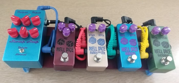
As an aside all of these pedals are made with machined(not die cast) Hammond sized aluminum enclosures from Ebay (alpinetech), which I etched and anodized. You cannot properly anodize die cast enclosures because of other ingredients that are mixed with the aluminum…so you have to get CNC milled enclosures if you want to anodize the enclosures.  I discussed my home anodizing process here: Anodizing discussion
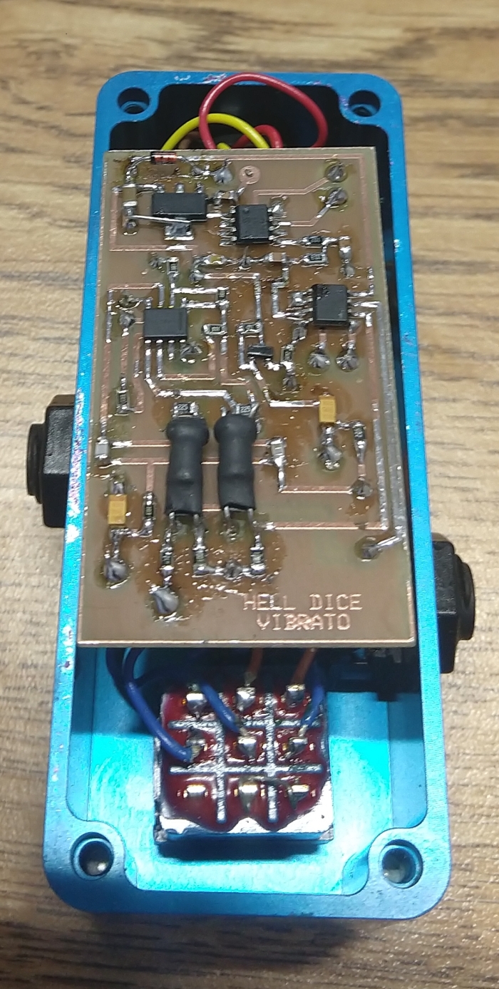
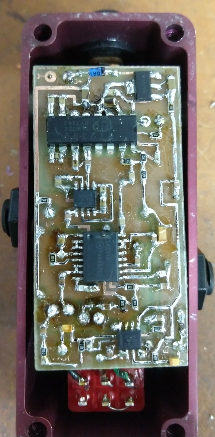
More Pictures:funkyfilt

vibrato board

delay board

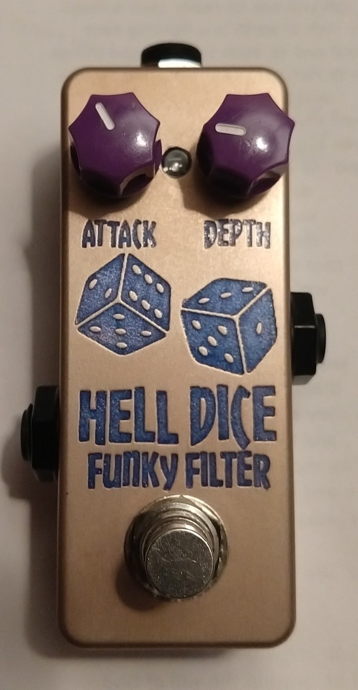
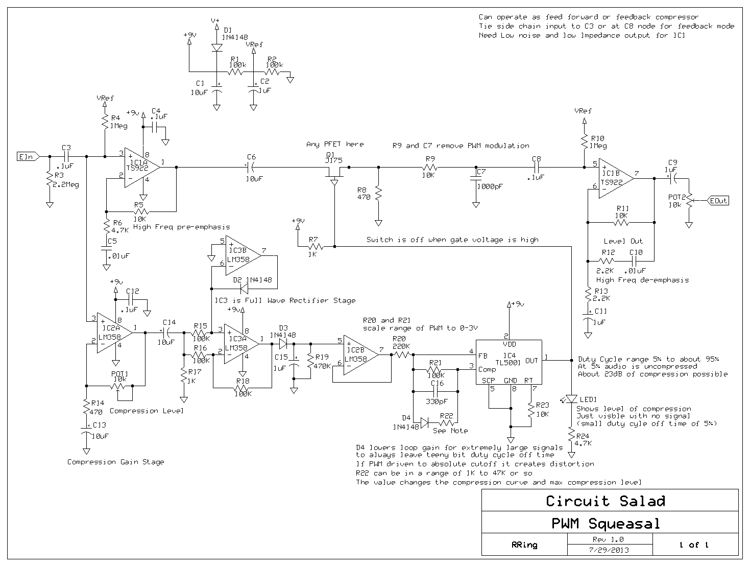
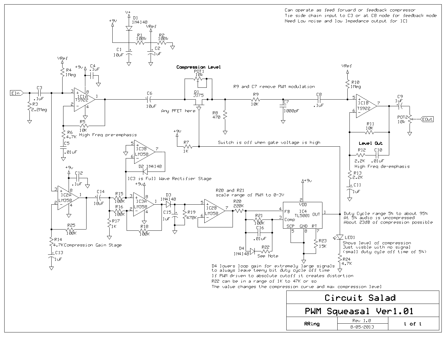
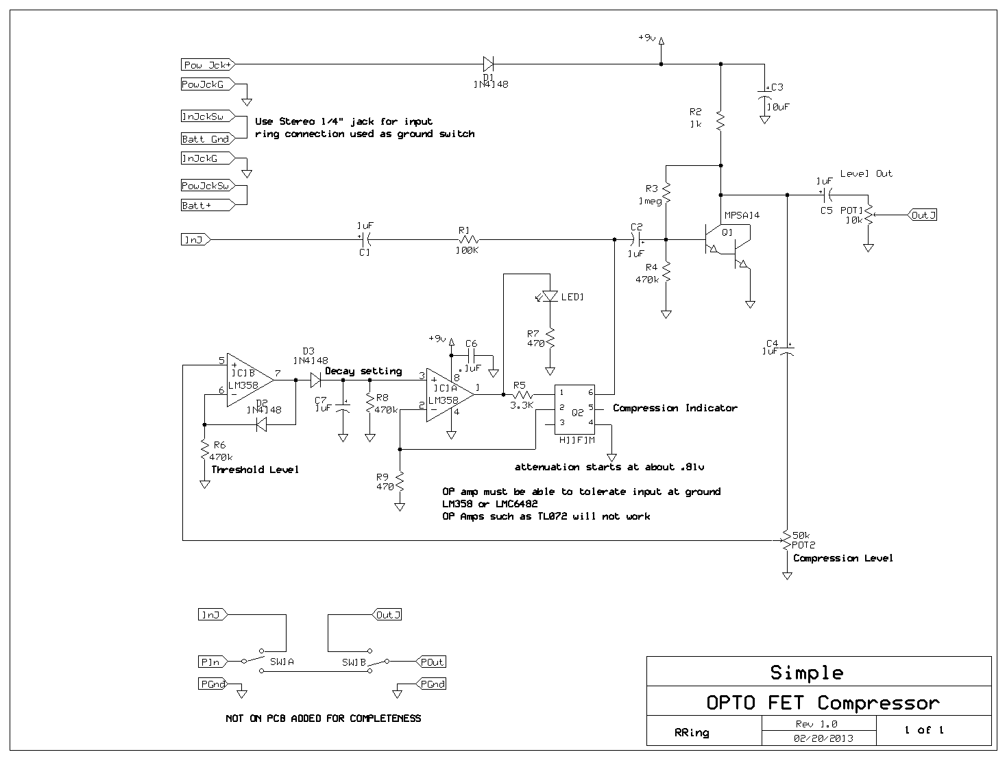
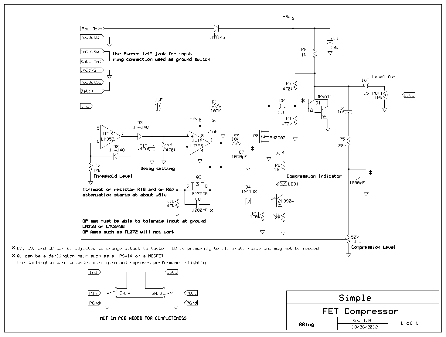
Links to Schematics and Design Notes:

A few notes: Many of the part choices are  not critical..like transistors, op amps and voltage regulators I use.. The LDR based effects will need tweaking based on the output efficiency of the LED/photo-resistor combo or if you use a commercial opto-coupler instead. The vibrato uses my pic based LFO…but it can easily be replaced with other LFO circuits. The delay uses a 8 pole switch cap filter IC but if desired, this can be replaced by using the unused op amp on the PT2399 IC as a low pass filter.

Compact Stomp Amp:

Hell Dice Delay:

Hell Dice Vibrato:

Hell Dice Overdrive:

Hell Dice Funky Filter:

Pedal Board Demos From Live Show:

Demo of Delay and Vibrato:

Demo of Envelope Filter(two minutes in):

The PWM Squeazal revisited

I have enjoyed my PW modulated compressor and decided to make a feedback(the original was feed forward) version with improved attack and shorter decay response. The result is excellent – I love this version. I use a Zetex current monitor IC as a full wave rectifier and this lets me really speed up the attack. So the response is super fast, very low noise, very low distortion, and very large dynamic range.


SchematicPWM COMP1_2_4

Link to design files:

https://www.adrive.com/public/PNQ67U/squeazal_design%20files.zip

Updated Squezal PWM Compressor Schematic, Layout and Demo

I have completed the PWM compressor design and created a layout to fit a 1590B enclosure. The design has been simplified some and has excellent performance both in feed forward or feedback mode. I removed the full wave rectifier circuit. A simple compensated peak detector works fine. I also implemented a analog switch instead of the PFET.   It provides a little more duty cycle range and significantly more input  headroom.

The original blog post for reference:

https://circuitsalad.com/2013/08/04/coming-soon-the-pwm-squeasal

The schematic is highly annotated – the original PFET switch can be used in place of the analog switch if desired.

Schematic Here: updated(9/12/2013)

Compressor Demos:

Link to Design Files: (Done in epresspcb single sided thru-hole)

https://www.adrive.com/public/PNQ67U/squeazal_design%20files.zip

To scale PDF image of layout for toner transfer: (you will still need to look at the expresspcb layout to see part designators)

Click to access squeazal-single-sided.pdf


PWM Compressor updates

I did some experiments and found the PFET switch has a limitation of about 1.6 volts total swing it can tolerate without clipping (using a 470 ohm load) you can get about 2 volts max with a higher  load of 4.7K or so. This is perfectly fine for most guitar applications.For more headroom you can use a an analog switch such as the TS12A4515. A number of manufacturers make this device. It is a normally closed analog switch. Of course others will work also. Using this as a switch basically makes the supply rails the headroom limit. I am going to play with the circuit some more and come up with a board layout and will post my final design in a few weeks.


The PWM SQUEASAL

I spent the last week working on a simple feed forward compressor using the TL5001 pulse width modulation IC to create variable pulse with switching circuit where signal output approximately linearly proportional to duty cycle of a 500KHz switching signal. The benefits of this include: very low noise, low distortion and lots of attack/decay flexibilty. I had some problems with noise early on but now the design shows great promise. It can work either in feed forward mode or feedback mode and has tons of possibilities for modification and refinement. Hopefully someone else can play with it and come up with some improvements. It is super quiet because no gain is changed of any amp stage – just the signal level itself. Other switching elements are possible, but the PFET works very well.

Schematic:

Here is an alternate version which I may like a little better where the compression ratio is controlled by simply bypassing the switch:

Video Demo:

PCB layout coming soon:

Some Possible Value Mods for the Simple Opto Compressor

There is another builder/designer Jon who has experimented with a number of my compressor circuits. He recommends a lower value for R1 of around 22k instead of the 100k in the schematic. This will lower the max compression a little, but will help with stray capacitance roll-off of high end.  It should work fine.  It will load the guitar pickups a little with heavy compression. Also the diode peak detector is biased in a more linear range by changing R8 and R6  from 470k to 47k and C7 from 1uF to 10uF. I think these values will work a little better.

Over my choices are:  100K for R1,  47K for R6 and 10uF for C7

The OPTO compressor revisited simple and works well

I have been playing with all sorts compressor ideas and the circuit below is about the simplest thing I have come up with that works well. It uses just a handful of parts and needs no critical adjustments. It has fast attack and slow decay – which I find the most useful  for guitar.

here is the schematic:

https://circuitsaladdotcom.files.wordpress.com/2013/03/simple-opto-comp1.gif

Additional notes here:

https://circuitsalad.com/2013/03/30/some-possible-value-mods-for-the-simple-opto-compressor/


link to ExpressPCB layout:

http://www.fileswap.com/dl/PFYBP3Gwp4/

It utilizes a number of features from my other designs and I have also integrated some suggestions from other designers (like using a darlington for the amp stage).

This design has the folowing features:

a  H11F1m OPTO FET variable resistor to control gain.

a darlington transistor as a shunt/shunt feedback amplifier. The biasing and feedback (from the collector to base) is critical to the design. The reason is that it keeps the voltage across the OPTO FET very low so as to keep it’s behavior linear. With out this feedback – there can be distortion.

LM358 beef stew op amp as a compensated diode peak detector and as a current mode amplifier the drive the H11F1m OPTO FET variable resistor.

The LED indicator is tied to the compression feedback loop and indicates compression level with variable brightness.

Demo  comming soon.

Simple Mosfet Compressor MODs

Another designer tried my mosfet compressor using a darlington pair as the gain stage  device Q1. He described some improvements in performance – so I tried this as well. I love it! Using a darlington such as a MPSA14 (or a homemade one) is a drop in replacement for the MOSFET Q1. It gives a little more gain and reduces noise in the control loop slightly (allowing more freedom in changing and or eliminating C7, c8, C9). I definitely can reccomend it.

New Schematic:

https://circuitsaladdotcom.files.wordpress.com/2012/11/mosfet-compressor1.gif

New compressor design – updated 10/28/12

Here is the schematic for a new compressor design, which has very small parts count but flexibility in threshold, attack and decay settings.

The design uses generic NMOS FETS such as the BS170 or 2N7000 and the only critical part is the one dual op amp which needs to tolerate voltage swing at or  below ground. I am using a LMC6482 but others will work. Another designer built my original compressor using the LM358 and after looking at the data sheet believe it will work here as well.

I am using a 2N7000 as a voltage controlled resistor and it works well but cannot tolerate a drain to source voltage of even 100mV. I solve this by using shunt feedback from the drain to gate in the amplifier stage. This creates a cancelling signal at the input node, proportional to the gain, which reduces the net voltage seen across the 2N7000 down to tens of mV(with a 2 volt input).

The 2N7000 has turn on voltage starting at about .8 volts. The circuit has a 2N7000 configured as a supply independent voltage reference which provides the bias for the voltage controlled resistor. This reference is adjustable and can be used to set a variable threshold of compression or fixed at whatever threshold desired.

This design also uses a simple op amp peak detector which would be normally used in a sample and hold circuit. A bleeder resistor is added to create a decay response as desired. Because a peak detector such as this tracks instantaneous level changes – it needs to have it’s very abrupt shifting of output level smoothed out to eliminate sharp noisy spikes as the amplitude changes rapidly. This is achieved with a simple low pass integrator on the input of the 2N7000 voltage controlled resistor. This smoothing filter sets the attack. The peak detector can use just about any diode. I am using an LED which lights up and varies in intensity with respect to the amount of compression. This provides a visual indicator of how much compression is occurring. No adjustments are required to use different diodes.

In all, you can adjust the attack, decay, threshold, compression level (from 1:1 to greater than 3:1), and output level with this design, and it only uses three mosfets and one op amp.

Check out the schematic here: Consider this obsolete….. look below for improved design

https://circuitsaladdotcom.files.wordpress.com/2012/10/simple-compressor.gif

Update: I am changing the design of this compressor somewhat to eliminate some noise caused by the closed loop peak detector. The updated circuit is below. It uses an open loop compensated  peak detector instead of the closed loop type. Also I separated out the compression level indicator – which really works well. It has the benefit of giving visual indication of threshold adjustments which can be set by R6 and R10.

I don’t need the final buffer either because the threshold settings and control loop gain allow the output match input level at max compression.  Many of the component values can be adjusted so expect to play around with some values. Currently, I am using : R6(100k), R9(1Meg), R10(10k), C10(.1uF). Changing R9 and C10(smaller cap and larger resisitor) lets the op amp slew a little faster – no big deal. If I have any big revelations that something is better – I will post it!

New Schematic:

https://circuitsaladdotcom.files.wordpress.com/2012/11/mosfet-compressor1.gif