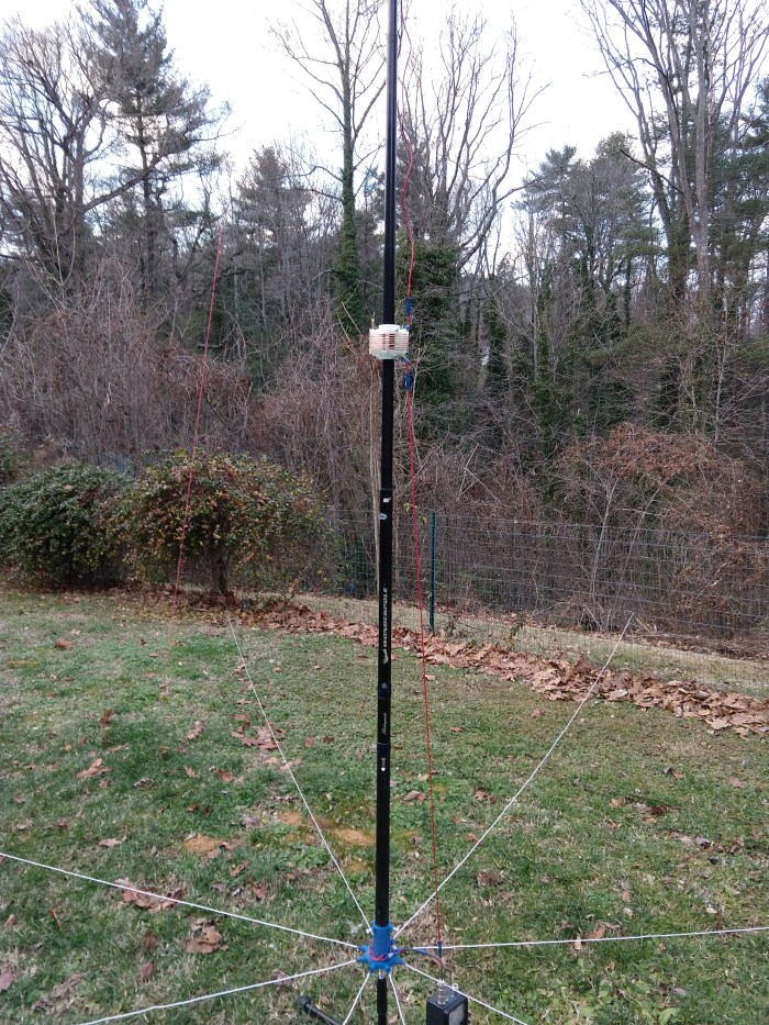
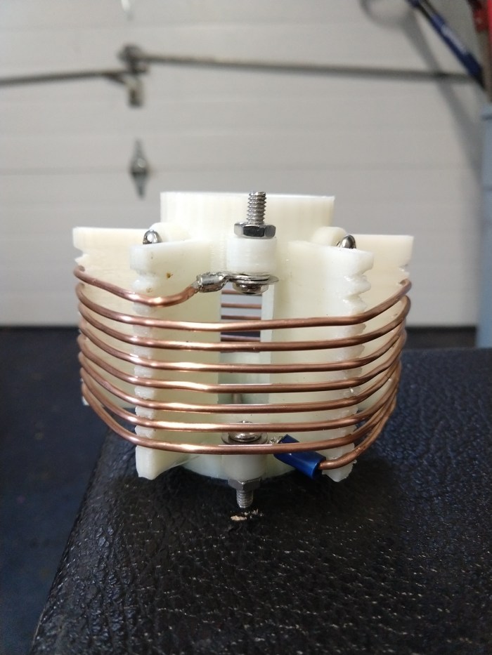
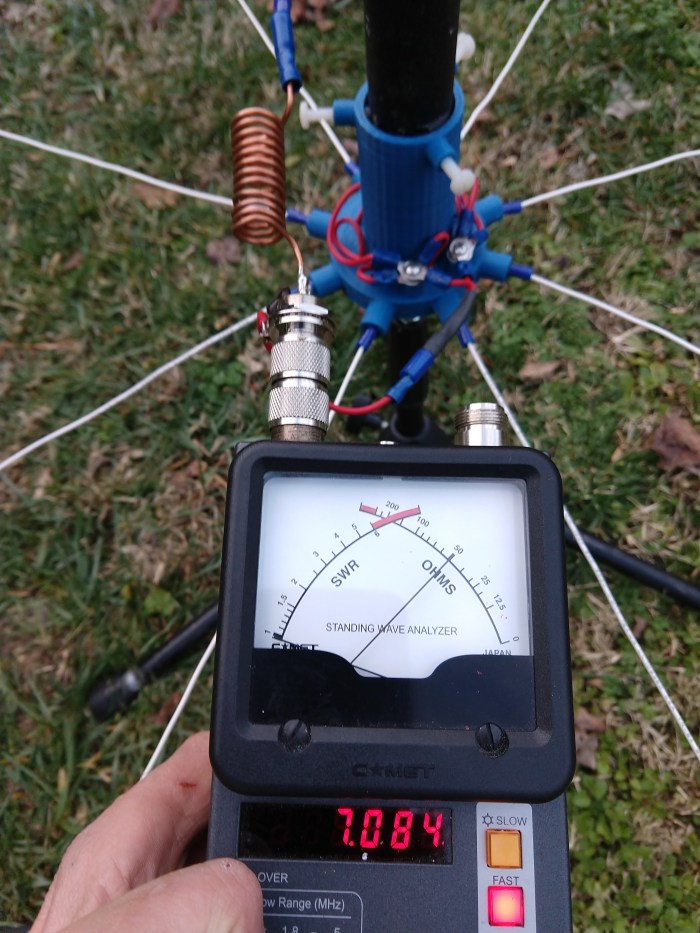
I had an old broken 20 foot fishing pole that only had 16 feet of length so I decided to see if I could make an effective half size 40 meter antenna with it. Here is what I did. I used a capacitive hat to increase the radiation resistance of the antenna considerably. There are 8- 15 foot radials suspended a little less than a foot above ground. Finally, I made a small loading coil to tune the antenna up to the center of the band (7.100 MHz) for CW. I first tested a full size vertical to optimize the ground plane. By suspending the radials by only a few inches above ground, significant improvement was achieved . With 8 half size radials 10 inches above ground (compared to 4 on the ground), the measured loss went from about 20 ohms to 4 ohms. My loading coil has a measured Q at 7Mhz of about 300…with about 1 ohm of loss. The form was printed on my 3D printer out of HIPS..which is a low loss RF material. So my total system loss was about 5 ohms. With the HAT top load, the 17 foot antenna had a total impedance of 20 ohms. This means I had a total system loss of only 1.25 db…which is not bad. the full size antenna had a loss of about .5 db … so really the difference is negligible. Finally I matched the whole antenna to 50 ohms with a little L network connected at the base. I like to use crimp style bullet connectors for all wire connections because they provide quick disconnect and you can field repair(crimp) without need to solder anything(nice for portable setups).
I use it for QRP work on CW at about 1.1 watts. The antenna is a solid performer and it is very portable and easy to breakdown/setup. I can hear my signal on the many of the web based SDRs around the country. and have made numerous casual QSOs with it. Six or Seven radials work well also..you start seeing some more loss when you go to four radials but it is still usable even then.
View of Top Load( 2 -8 inch strips of thin aluminum)
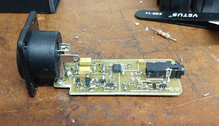
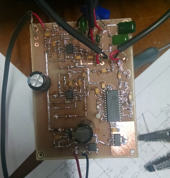
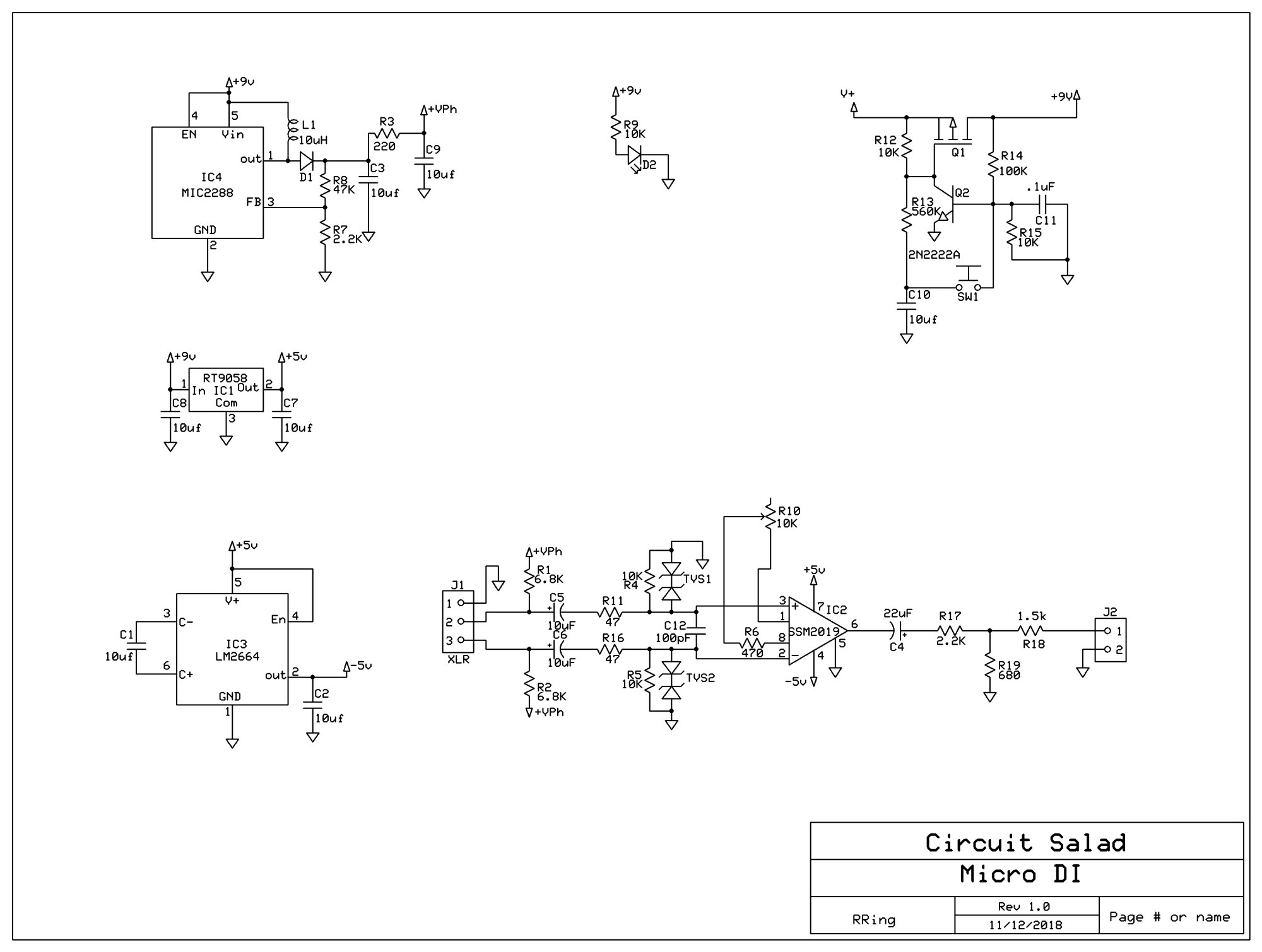
I frequently use my phone to record video for my blog and for my music projects…but I have been frequently frustrated by the limitations of the internal microphone embedded in the phone. So I created this circuit to provide a means to use a high quality Dynamic or condenser studio microphone with my phone. The circuit operates from a rechargeable 9 volt battery and plugs into the standard 1/8 inch four ring audio connector. It provides phantom power at 28 volts…which works fine …you typically don’t need 48 volts It utilizes a SSM2019 balanced microphone preamp IC, operating from a dual polarity charge pump power circuit at +-5V. At the output you need to provide a 2.2k resistive signature such that the pone can detect the microphone connection. The circuit also employs my simple momentary latching switch circuit which I often use and is described here at circuitsalad. Everything about the circuit is straightforward but the phantom power over voltage protection circuitry merits discussion. Basically, the isolation capacitors C5 and C6 are slowly charged up by the phantom supply but depending on what is plugged and unplugged can be be discharged very rapidly into the preamp input circuitry. This will be destructive and requires circuitry to shunt this energy to ground and dissipate it. This is accomplished by means of TVS1 and TVS2…which are prepackaged back to back zener diode. However the issue arises that simply using large zeners or transorbs is not a good idea because they have large reverse bias junction capacitance…which creates distortion as it modulates. To prevent this, I chose a very tiny 9 volt transorb. The one I chose (DF2B6.8ACT.L3F) has only a few pF of capacitance and is very small(402) surface mount package. The device works great but can only sink 1 amp peak. This further requires series resistors R11 and R16 to help limit the surge current to less than 1 amp at 28 volt. R1, R2, R4, and R5 must all be precisely matched in order to maintain circuit balance. R4 and R5 are required to provide a absolute ground reference such that the output does not float to some common mode DC value above 0 volts. The gain of the preamp is -6dB -20dB and is adjustable by means of R10. The reason for the negative gain is the use of an attenuation network that also provides the 2.2K resistive signature for microphone detection. The attenuation is required because of the inherent gain of the phone circuitry, which is easily overloaded.
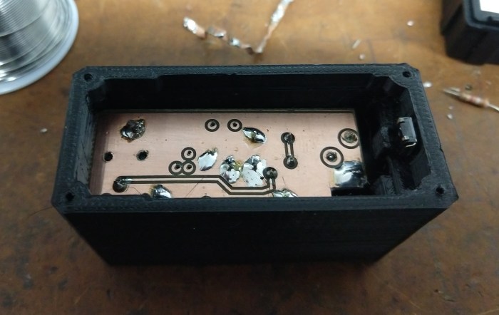
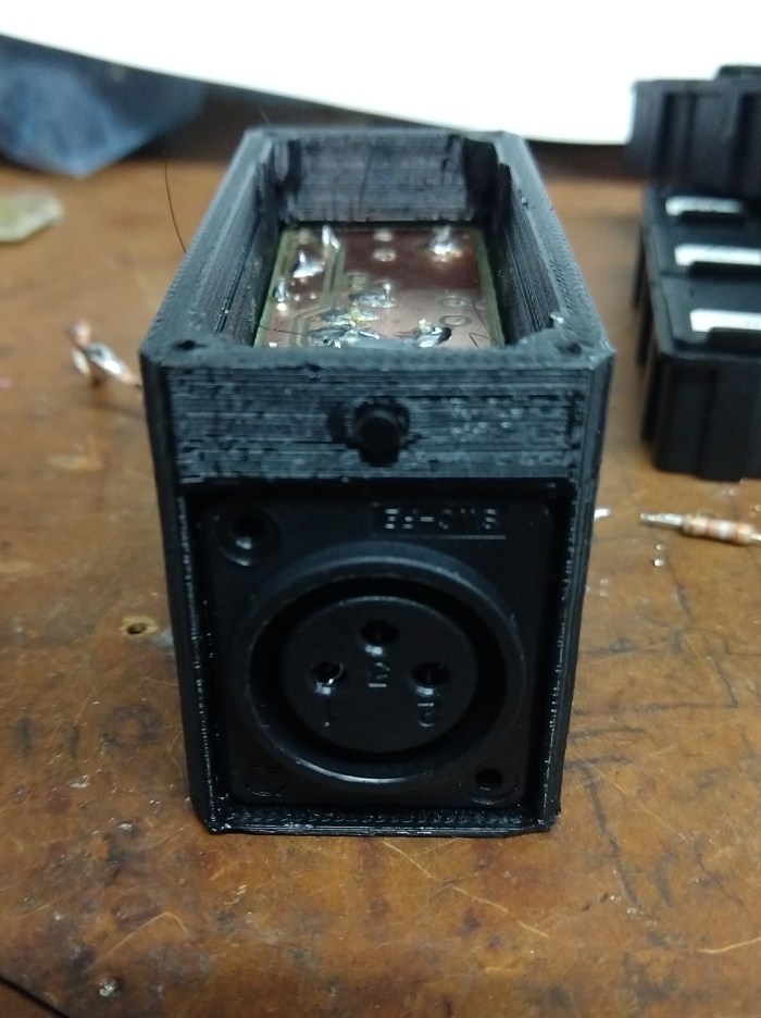
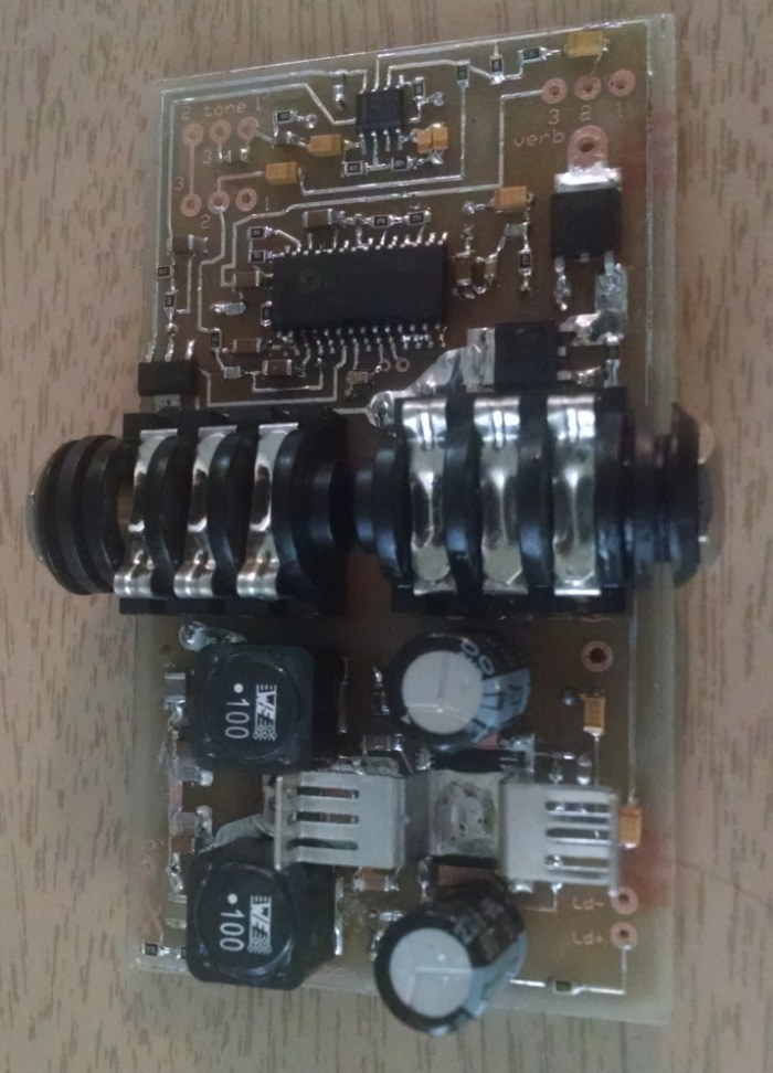
As seen in the pictures below, the circuit board fits in a compact 3D printed enclosure. The battery sits above the circuit board and is enclosed by a a top cover. I use a rechargeable 9 volt because the device draws about 30mA in total.t I included a 2.5mm circular power plug as a charging jack such that the battery can be charged without removal from a generic 9 volt battery charger.
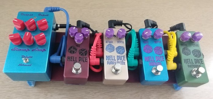
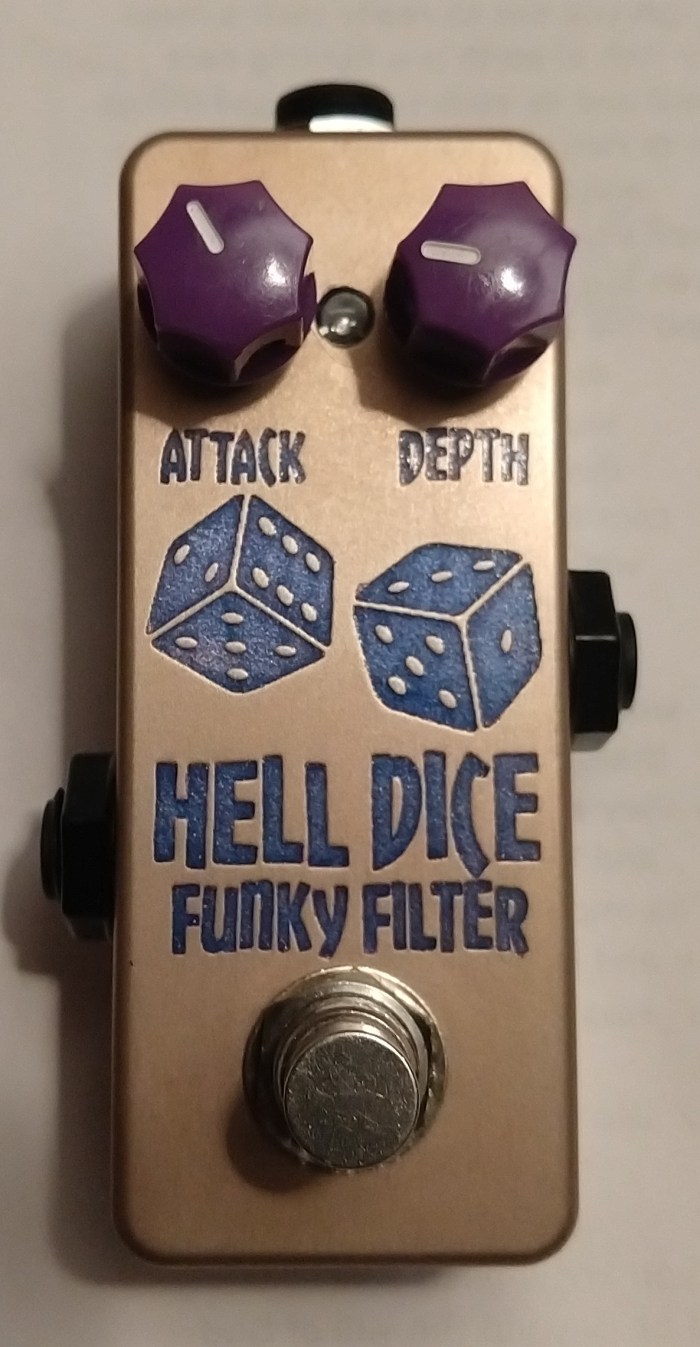
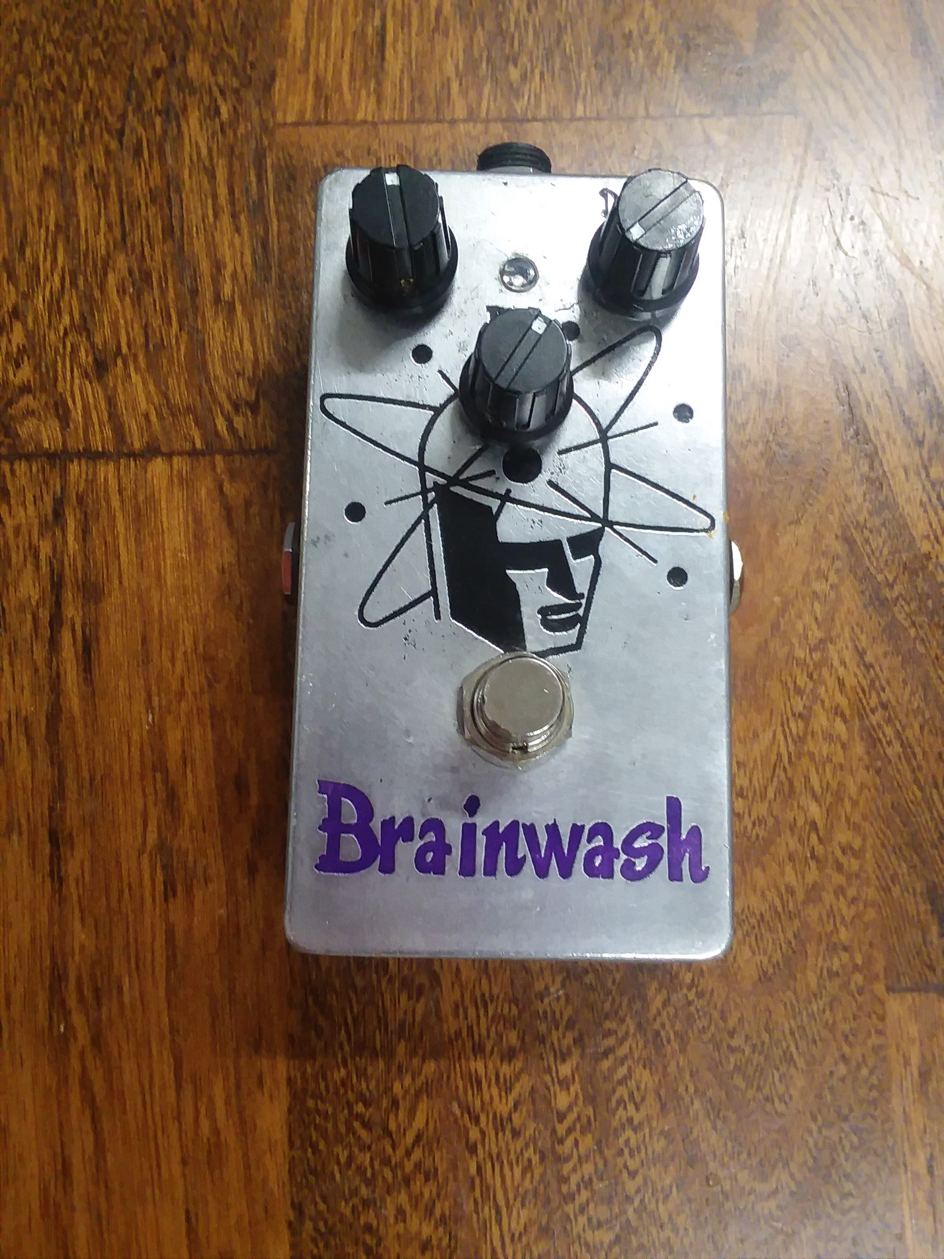
I have been performing way more than I use to! I play club gigs twice a week or more these days…and as a result, my relationship with my rig has really changed. Which is to say, my perspective on what I actually use and what features matter most, has evolved. My conclusions are these: I want small, light weight rugged equipment…I don’t want too many knobs or complexity. I like to use a few basic settings and sounds and that is it. So I have designed a compact amplifier and set of small 1590a form factor pedals to create a complete amplifier/pedal board rig that weighs a couple of pounds and is about 12 inches long and 4 inches wide. It includes: My 100 watt stomp amp with an auxiliary 9 volt output, a high performance PT2399 type delay, a simple but really nice sounding LDR based envelope filter, A very pleasing two stage LDR phase shift Vibrato and a hex inverter based overdrive with slightly different approach than the typical design.
My New Compact Pedal Board
As an aside all of these pedals are made with machined(not die cast) Hammond sized aluminum enclosures from Ebay (alpinetech), which I etched and anodized. You cannot properly anodize die cast enclosures because of other ingredients that are mixed with the aluminum…so you have to get CNC milled enclosures if you want to anodize the enclosures. I discussed my home anodizing process here: Anodizing discussion
More Pictures:
Links to Schematics and Design Notes:
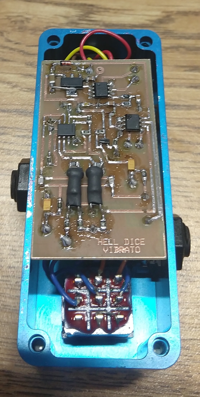
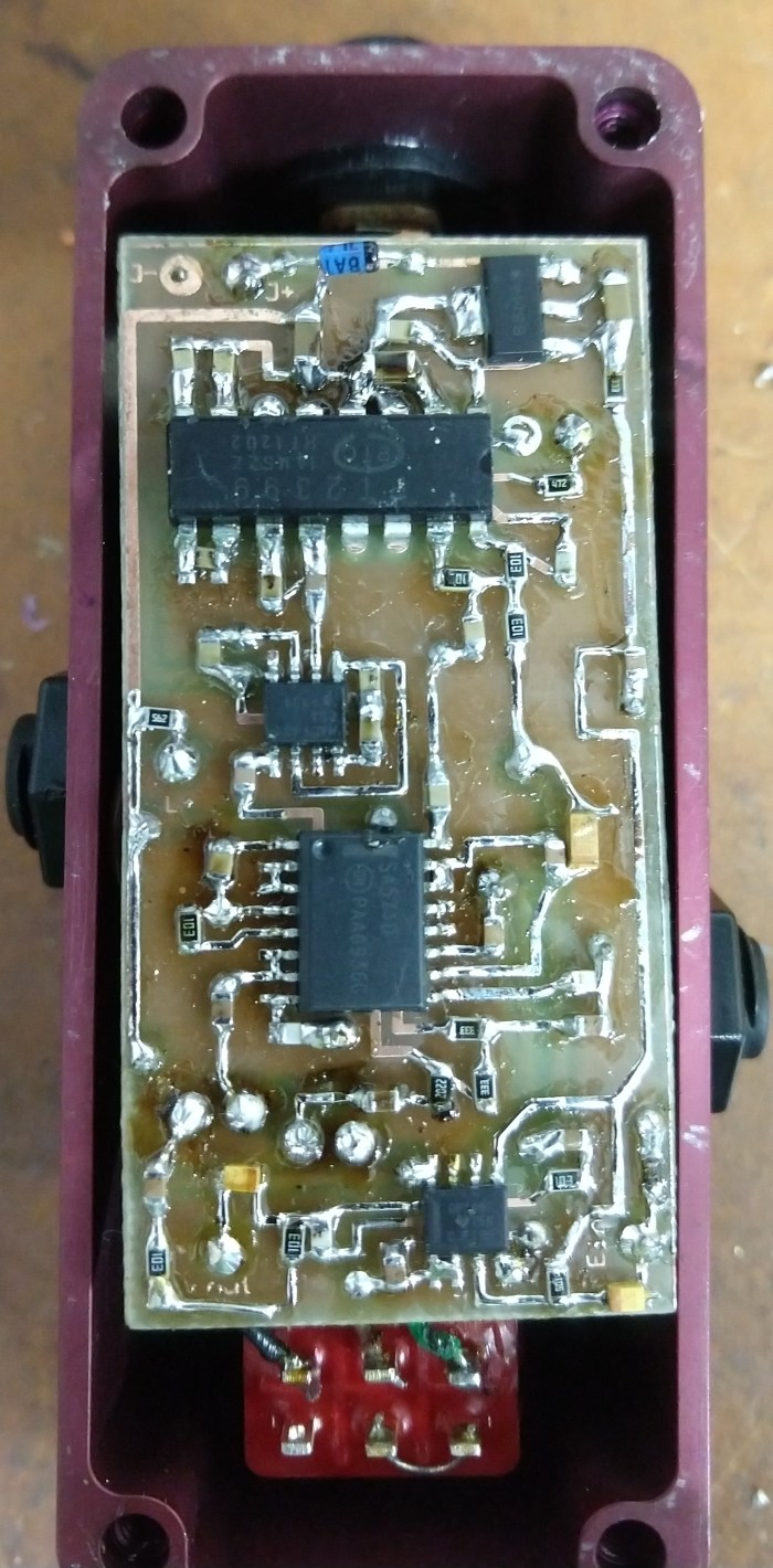
A few notes: Many of the part choices are not critical..like transistors, op amps and voltage regulators I use.. The LDR based effects will need tweaking based on the output efficiency of the LED/photo-resistor combo or if you use a commercial opto-coupler instead. The vibrato uses my pic based LFO…but it can easily be replaced with other LFO circuits. The delay uses a 8 pole switch cap filter IC but if desired, this can be replaced by using the unused op amp on the PT2399 IC as a low pass filter.
Vibrato is the slight changing of frequency of a musical note. This can be accomplished by means of a varying time delay in a delay line or by phase shifting and analog signal over time.
The delay approach works fine but creates inherent latency and can sound clownish. So I wanted to create an analog design.
A modulated allpass filter can be used to change phase over time (which is frequency). This analog approach can sound lovely but to sound really good has to linear in its sweep and be modulated in a sinusoidal manner. Both the design objectives are not trivial.
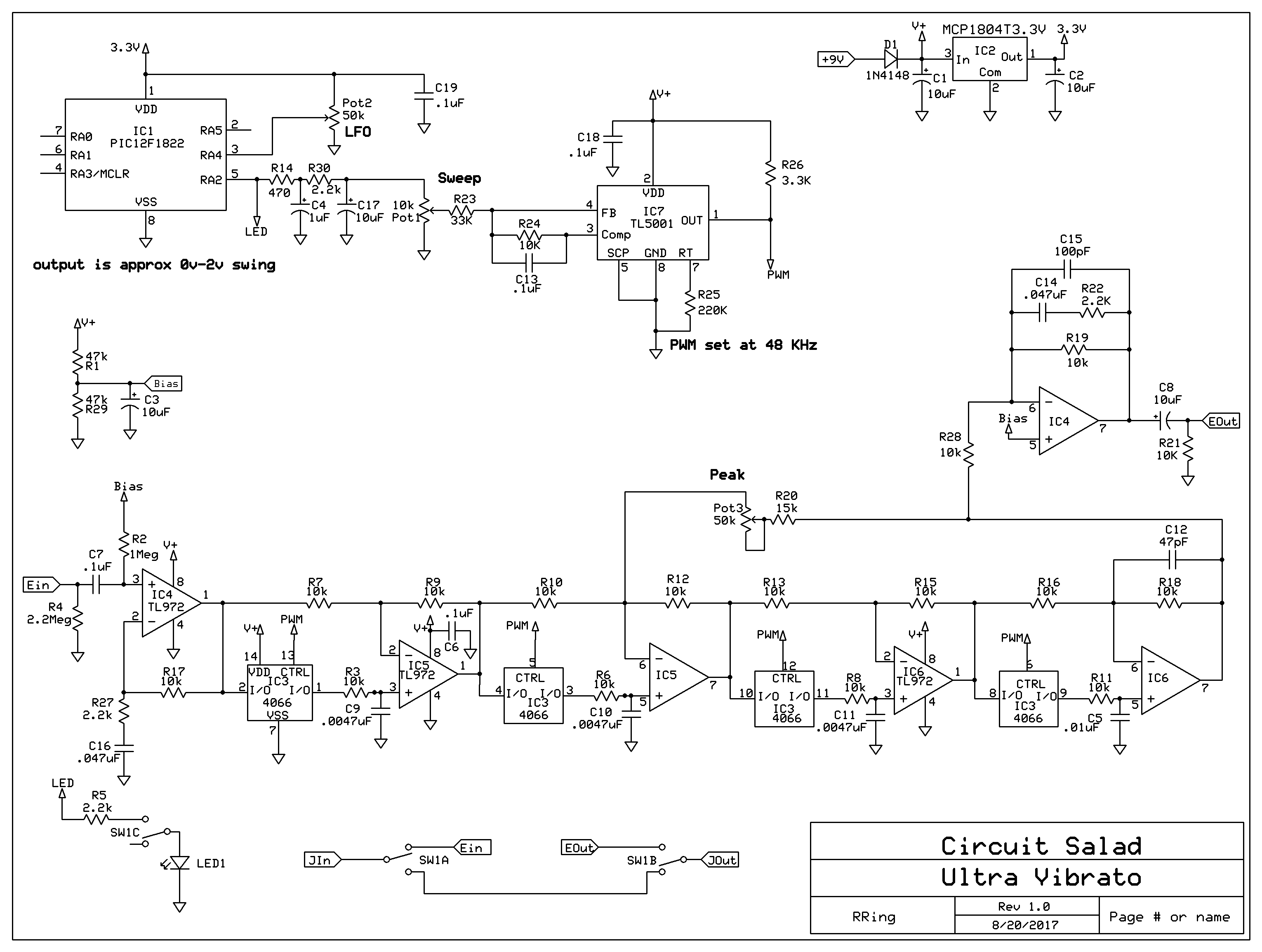
It occurred to me that my PWM phaser design does all this but simply mixes the original signal back in to create the phasing notches. So I modified the circuit and optimized it to simply modulate the filter and it works great. The PWM driven analog switches are very linear and the PIC DDS works great to create the sine wave modulation. I added some pre- emphasis/de-emphasis, adjusted some values and made an improved layout…so the pedal is super quiet. I left in the peaking filter adjustment to allow for some cool modulated filter effects along with the Vibrato. The range of PWM controls the extent(depth) of the effect at a given modulation rate and so the vibrato pitch bend level is easily adjustable. Keep in mind the faster the modulation rate; the pitch shift is also greater because a faster the rate of change of phase over a given time, produces more pitch shift. An alternate analog modulation circuit can be used if desired but the output swing needs to be limited from 0 – 2 volts.
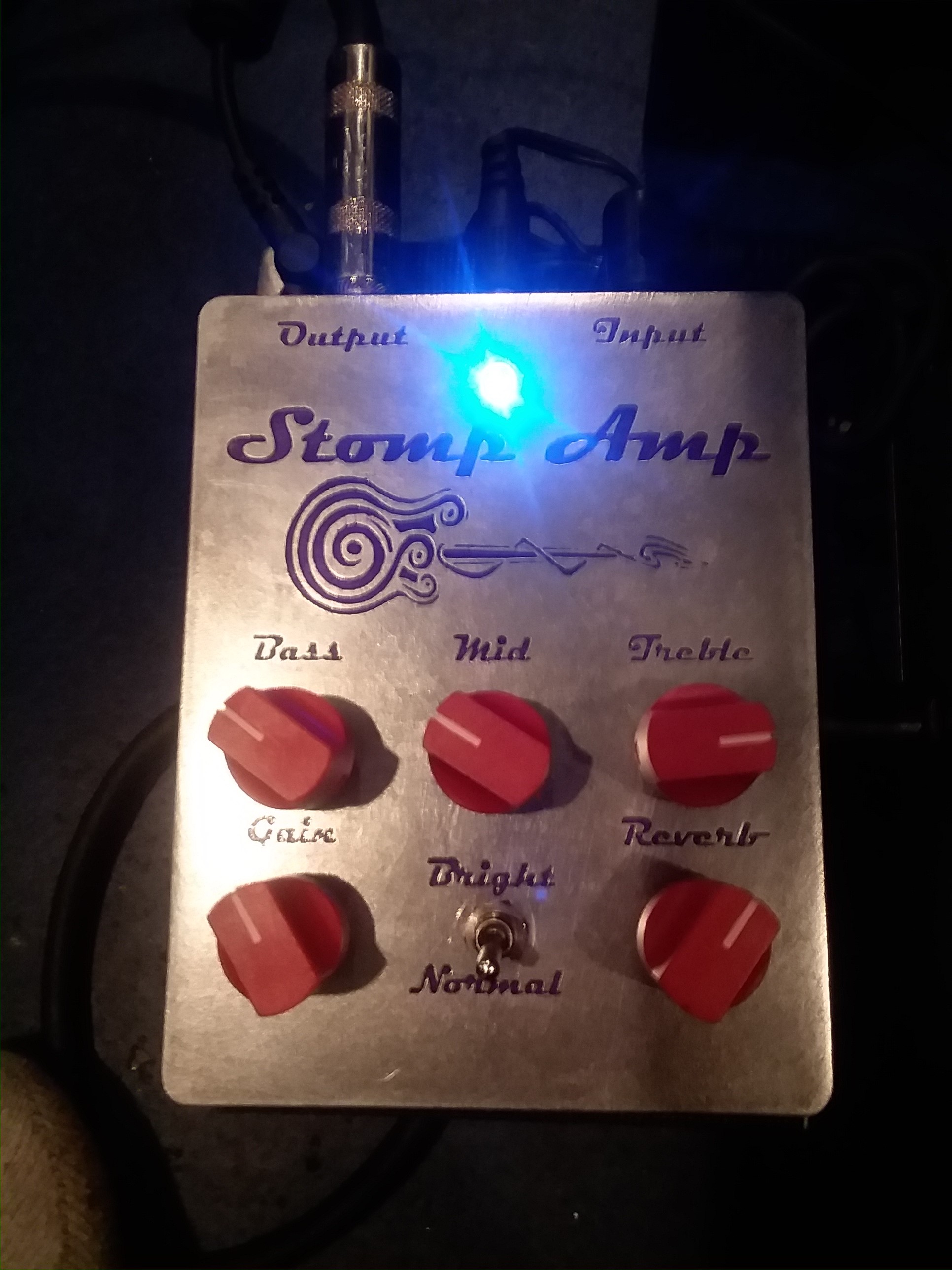
but with an enhanced tone stack much like that of the Polytone Brute amps and a JFET driver stage for the final. The normal/bright selector is quite useful as well depending on the pickup type and location.
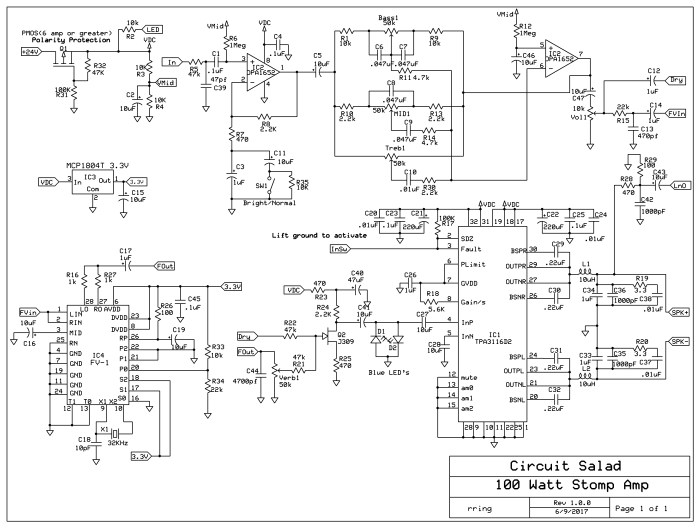
Here is a download link for the schematic and PCB in express PCB format(can be converted to gerber using freeware: copper connection)
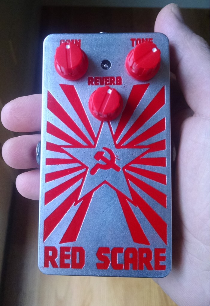
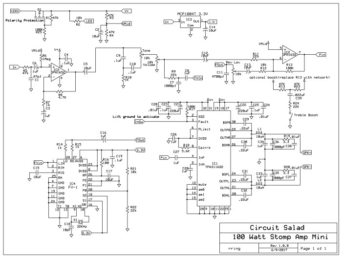
Continuing on my Stomp Amp theme; I have created a 100 watt (24V supply, 4 ohm load) guitar amplifier with FV-1 based DSP reverb and optional treble boost. It fits in a 1590b stomp box. Yes it really is a 100 watt amp!
It has Gain, a single tone control, and reverb level control. The reverb room size is set by a resistive divider(R21 , R22) and can also be made adjustable. It utilizes a TPA3116D2 class D amplifier IC which can be configured for mono or stereo output.
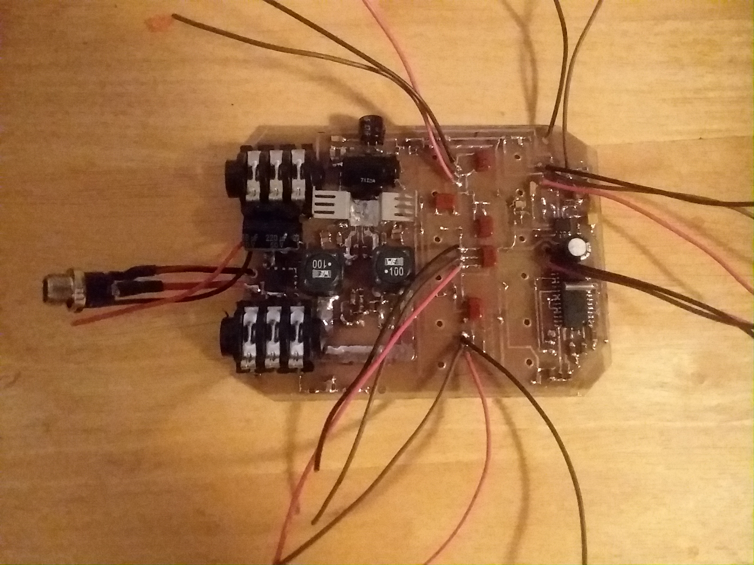
The amplifier sounds delightful. The class D topology provides greater than 90% efficiency. This eliminates the need for substantial heat sinking. The only penalty is that for guitar applications, pushing the amplifier to distortion does not sound so great. I use an overdrive pedal so I don’t care about this.
Update: I added a LED clipping circuit to make sure the input into the class D final amplifier is level limited(clips/distorts) before the final amplifier starts distorting
Link To CAD FILES: https://www.adrive.com/public/QpRQMX/RED%20SCARE.zip
The single tone control is surprisingly versatile. It alters the level and center of a MID scoop. You can get really FAT all the way to bright twang all with one control. The circuit can easily be modified to employ a more sophisticated tone stack if desired. The amplifier requires a 12-24V power supply with at least 4 amp sourcing capability. You can purchase a small lightweight switch-mode supply from Amazon for less than $20.00 that will work nicely. It is ridiculously small, lightweight, loud as hell, and sounds superb through a couple of 10″s or a single 12″ cabinet.
Quick Demo of built in Blue LED clipper limiter added to original prototype(you can see the LEDs flash as the input is clipped)
Below is a link to a tutorial on how bad ceramic capacitors are regarding holding their capacitance value under voltage bias. Basically the smaller the capacitor (physically) and the larger the voltage across it, the less the actual capacitance will be. I have always know this to be true but I didn’t realize it was as bad as describe below. This was a good reality check for me to make sure and select capacitors for a design carefully!
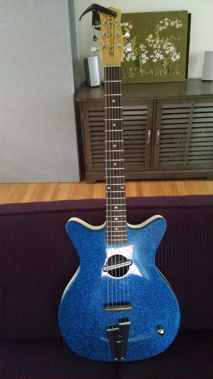
So I like sparkly guitars and decided to buy one. I figured I should get the goofiest thing I could find and so I decided on a Danelectro Convertible re-issue from the late 90’s!
I knew it would have issues…and it did! But fear not, this story has a great ending!
Danelectros are cheaply made guitars but do have some nice features. My convertible has a fantastic neck made of quality maple, but not too thick(good for my playing). The rosewood fretboard is almost a 1/4 inch thick and is also high grade wood. The frets are on the beefy side which I like. You need to remove the neck to adjust the truss rod but, this is easily done and you can loosen the strings but leave them on to do this. The bodies are made of masonite and plywood composites. These materials are nice in that they are stable and tolerate of temperature variation but god help you if they ever get wet! Yes they look cool, but besides the necks, the pickups are the big claim to fame of Danelectros. The lipstick type pickups have a unique sound with a scooped mid range and a very bright high end…probably from having less self capacitance and a lower winding impedance. I don’t actually like the sound for most types of music I play, so one of my primary objectives with this instrument was to get a punchier mid range without making the low end suffer or make it sound muddy. Also contributing to the sound is a tone/volume setup with a dual gang pot and a circuit I did not care much for. As shown in the picture above this is operated via two concentric knobs.
So this is what I did to make this a really well playing and great sounding guitar
1. I took the neck off and did a complete fret leveling and re-crowning. I won’t go into the details of the process here but I just started doing this and have done fret leveling on three guitars – all with stellar results! I highly recommend that guitar players learn how to level and crown the frets on their guitars. There are lots of tutorials on youtube. It is surprisingly easy to do(you need the right tools).It takes about three hours and makes such an improvement if your guitar has uneven frets(likely). You can get everything you need from Amazon..etc.
2. I adjusted the truss rod such that the neck is ultra close to perfectly straight. I did this to get the action even along the neck while allowing for the bridge to be adjusted up higher; so it has more tension across it. It plays better and it sounds better.
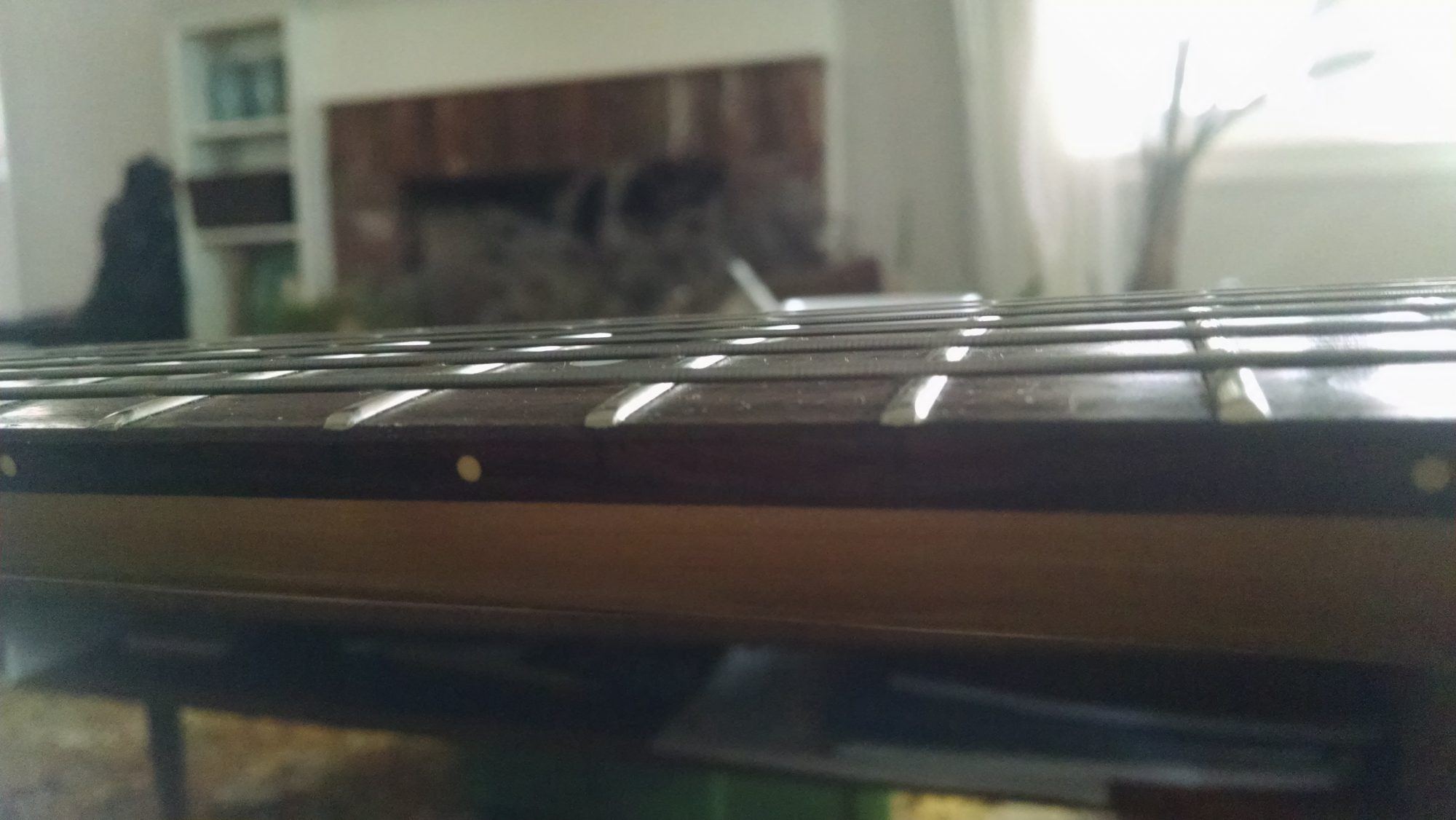
After fret leveling and truss rod adjustment, this guitar plays unbelievably well. This picture shows the action from frets 8-12. It just a little higher than a credit card along the whole neck with no buzzing or weird anything!
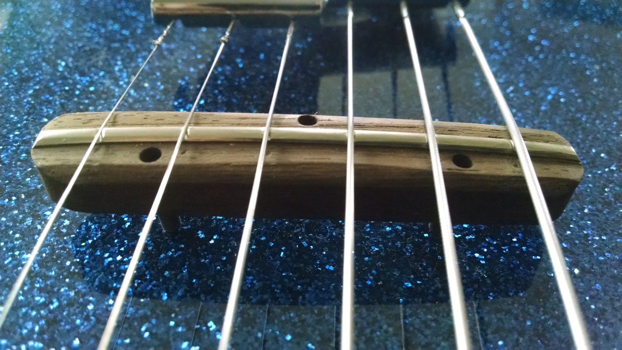
3. Modified the the floating bridge so the strings won’t slide all over the place (problem with these bridges). I simply carved a little notch for each string along the fret wire saddle. Note that I made sure the notch is deeper on the front such that the strings don’t buzz by hitting the front of the saddle when vibrating. I did this with a little triangle and rat tail file.
4. I designed and installed a preamp that is tailored to improve the tone of the pedestrian lipstick pickup that came stock on the guitar. This preamp uses an LMV641 low noise, low power op amp. It draws less than 150uA which is amazing. The Danelectro Convertible has plenty of room to put all kinds of stuff in it, but I just opted to make this tiny amp board and use a A23 12v battery glued to the back of the cover plate. You could use a standard 9v or two 3V coin cells in series, etc. The jack on my convertible was already a stereo jack so I was able to use this as an on/off switch for the preamp. The ring connection on the jack can be use connect the battery to the ground through the guitar cable plug. The preamp has a gain of two which could be adjusted if desired by changing R4 or R3. R6 and C3 replicate the load resistance and capacitance of the volume pot that would normally be present and can be adjusted to alter tone as desired. C2 provides super high frequency roll off for amplifier stability and does not affect the tone. C6 and R3 roll off the high end just a little bit. R3 can be a POT thereby creating a typical guitar tone control. A 10k POT is a good value to use in this case. C6 could be .1, .22 or .47uF depending on taste.
After adding the preamp, the pickup sounds fantastic. It still has the lipstick high end sparkle but with a fatter overall sound. When you turn down the volume, the tone doesn’t change either because the drive of the preamp is not loaded down by cable capacitance.I love it.
This is the preamp with the battery shown in the background. A 9 volt will work also.
Preamp Schematic shown above
5. I Changed to a single volume only control. My preamp has a provision for a tone control but I opted not to use it because I didn’t want to drill another hole in the instrument.
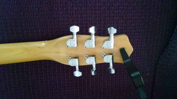
6. The Guitar came with really nice Gotoh tuners(not sure they are original). So I did not have to upgrade these, but this is not always the case. If You have a Danelectro with cheap tuners, change them out!
7. I adjusted the pickup as close to strings as I could. I found this to improve the tone. While it also boosts output, that’s not why I did it.
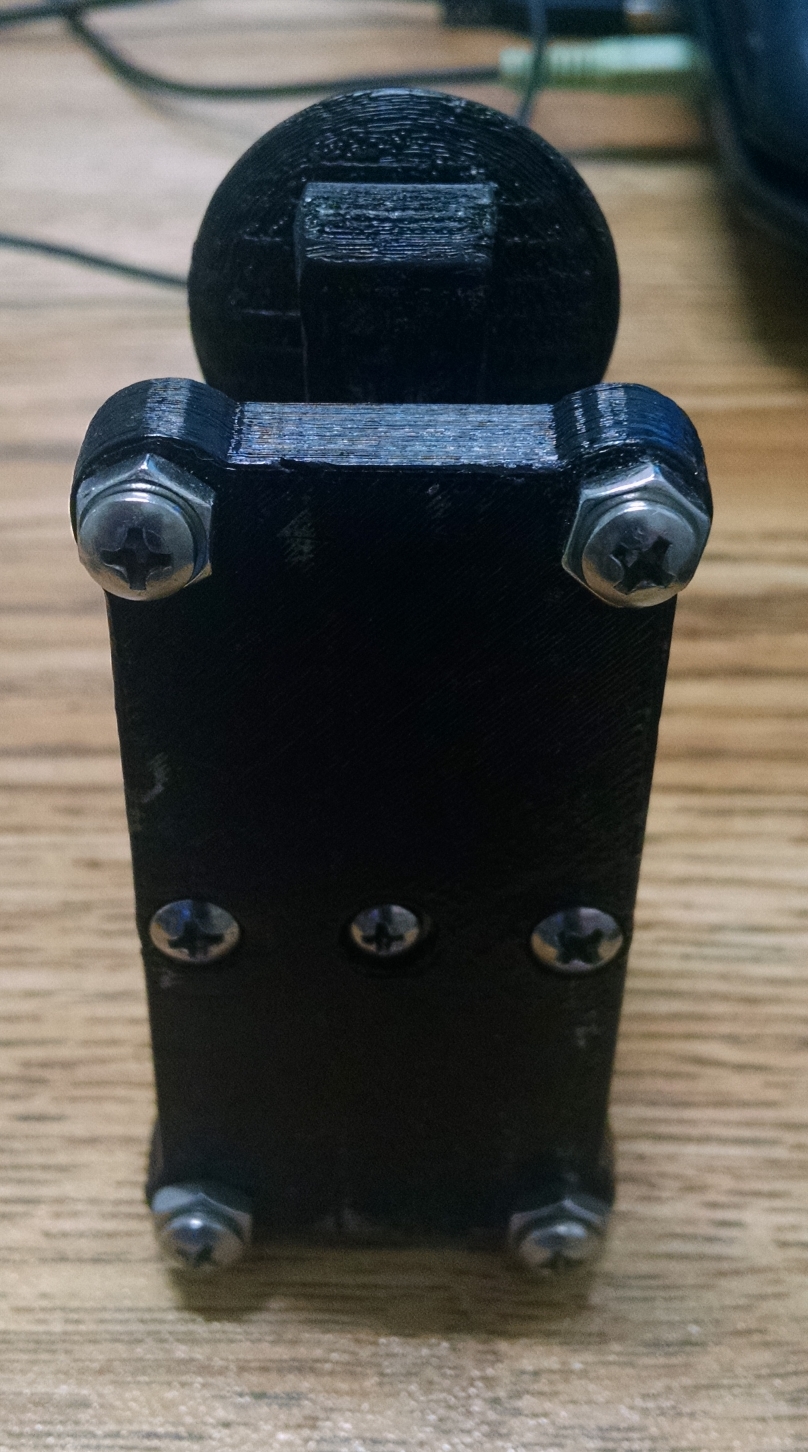
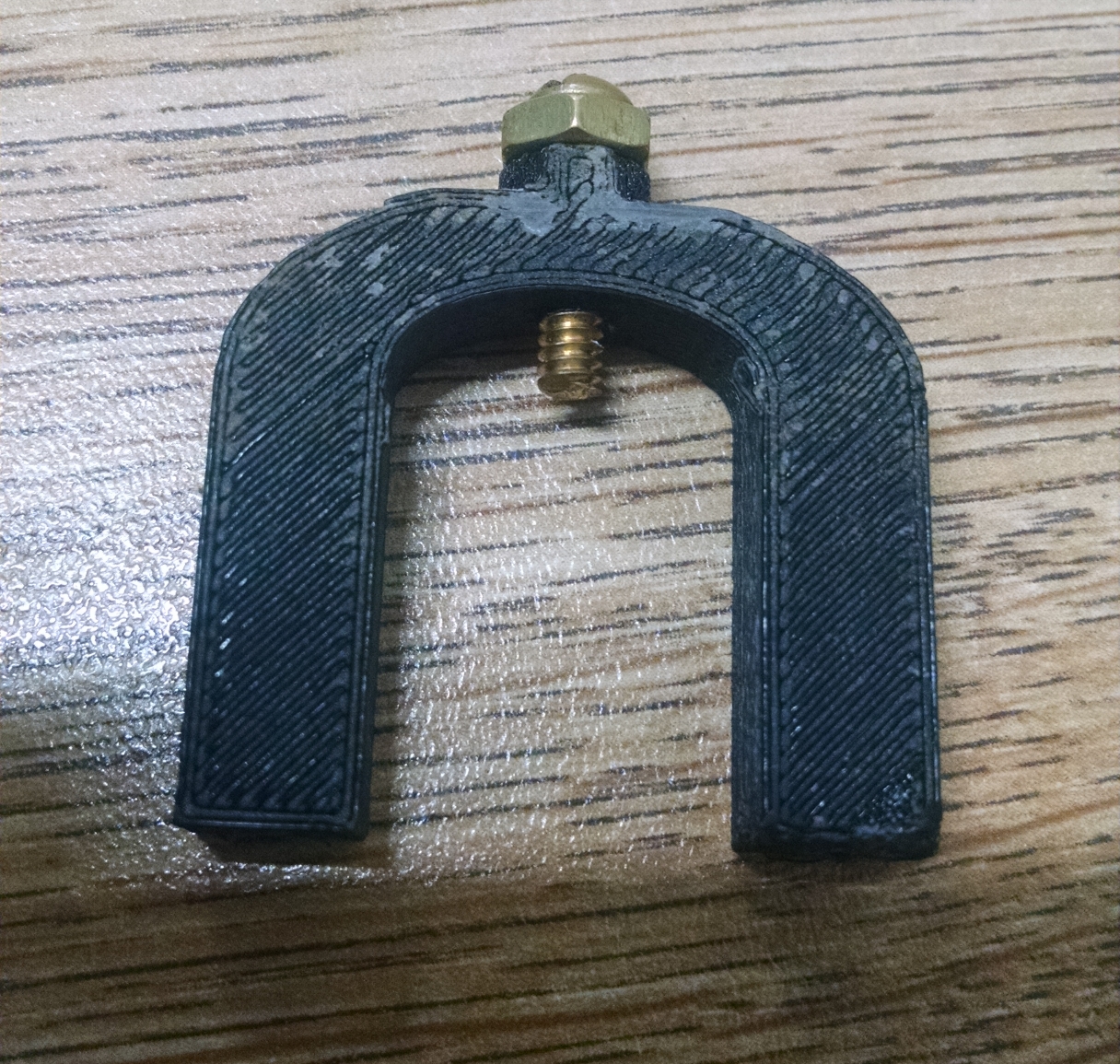
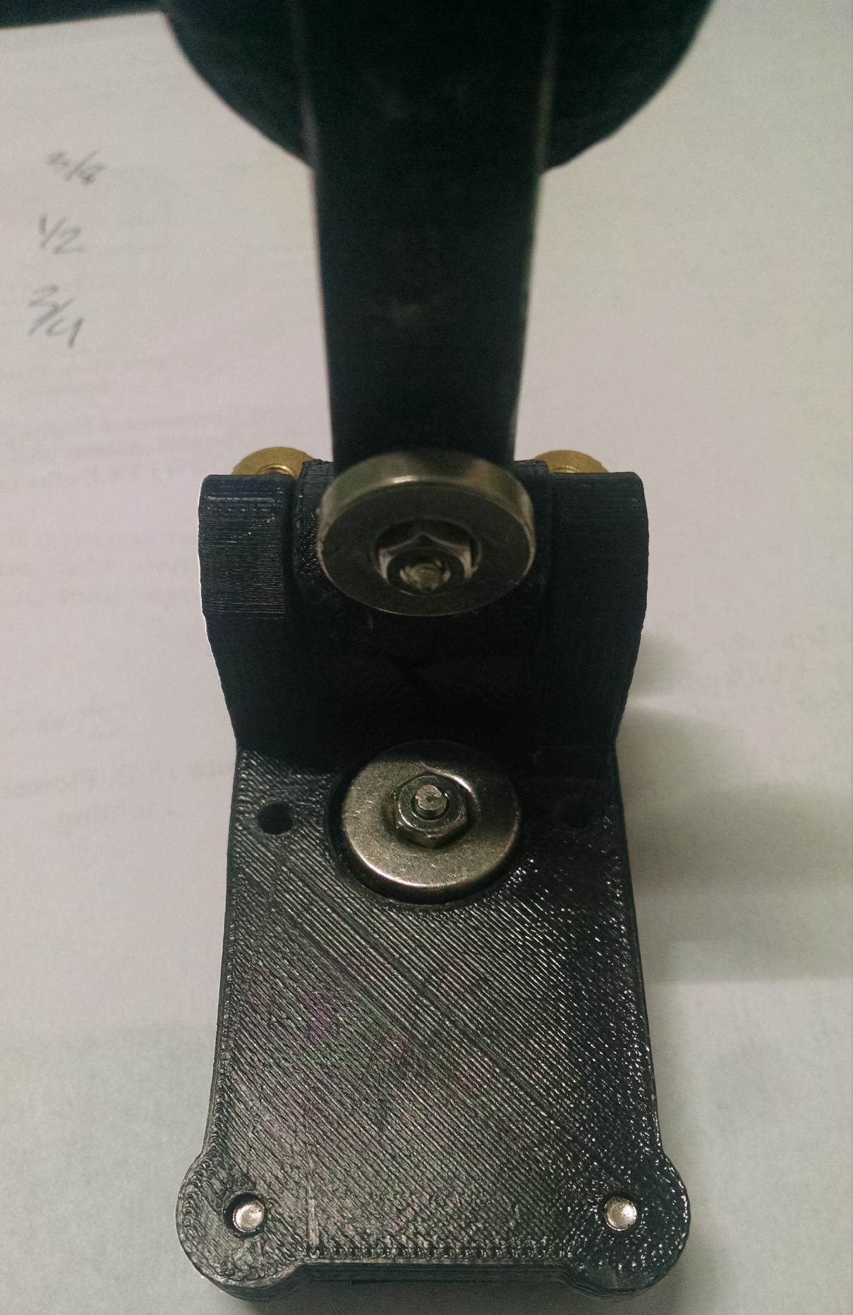
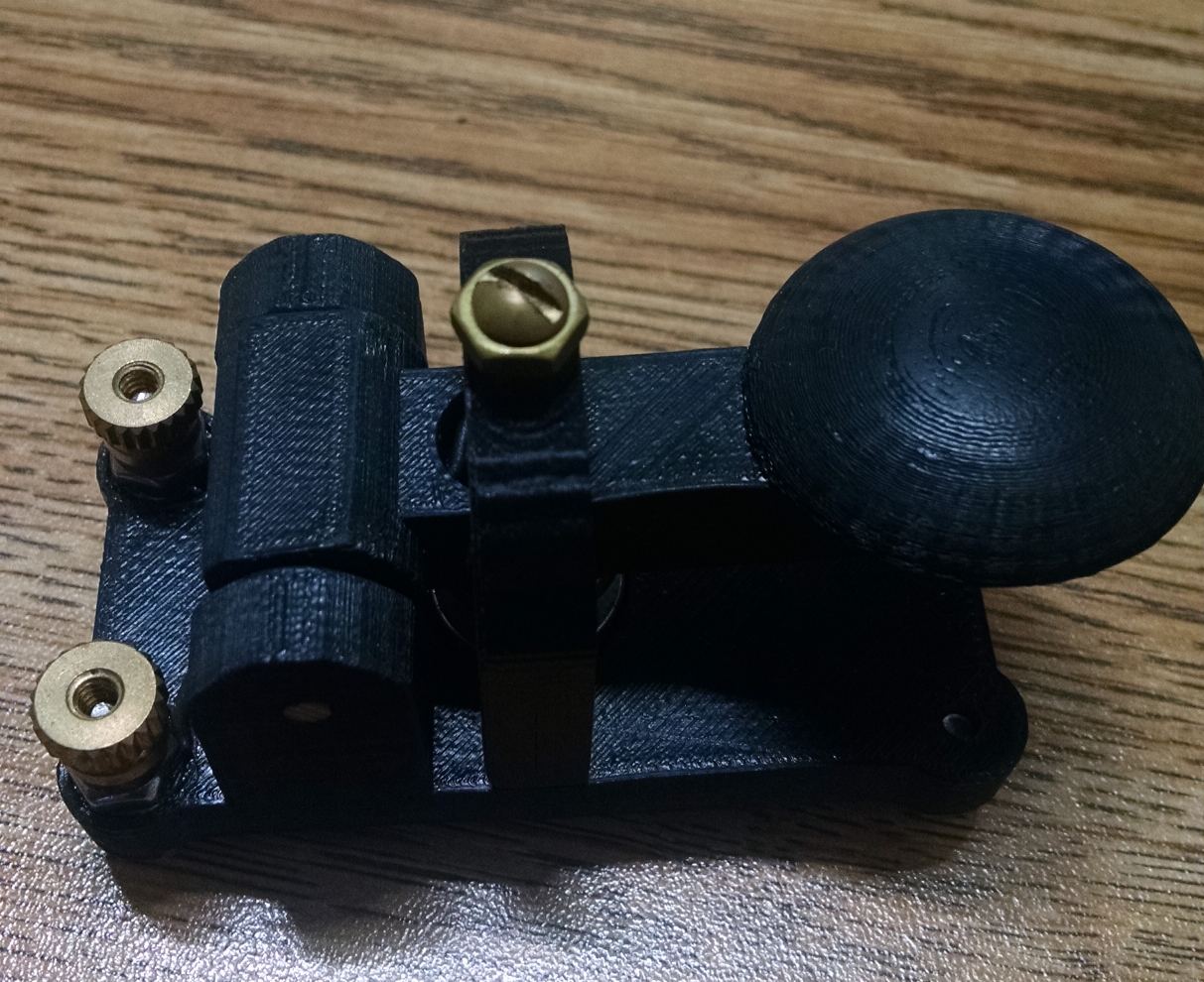
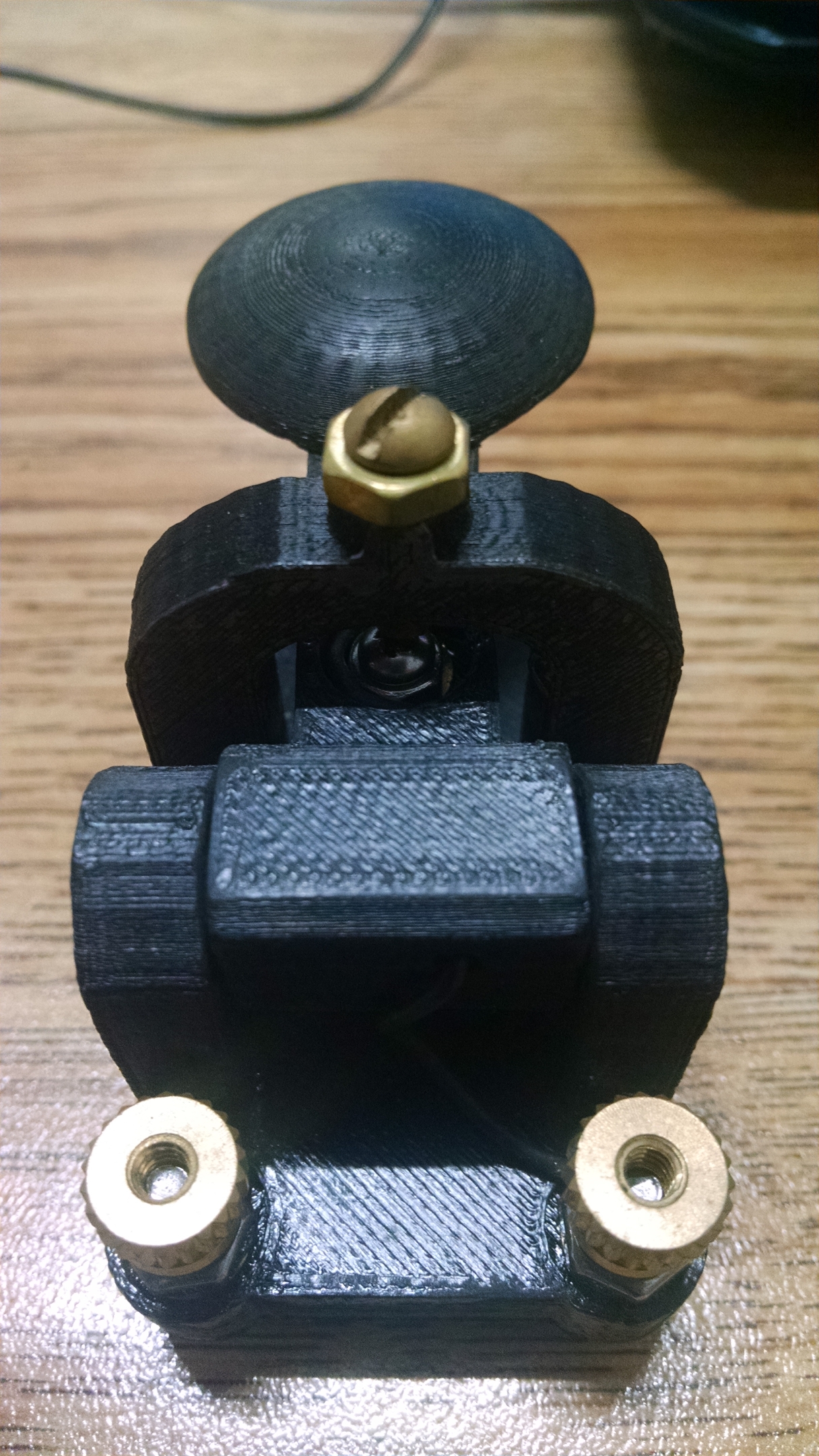
There are 3 files that print the base, key and upper bracket separately. All of the holes are included but they are undersized. Some you will drill larger and others are tapped. There is a horizontal hole in the key to run a wire back from the top key contact and the same is true for the base. I printed at 100% fill using ABS. HIPS would work well also. The magnetic damping instead of a spring works really well. The 4-40 contact screws need to be filed flat after being nipped to size.
Required Hardware:
2″ of brass 1/8″ rod (for hinge point)
2 3/8 6-32 screws (front legs)
2 1/2 6-32 screws (mounting upper bracket)
3 3/4 6-32 screws (Key adjustment and back legs)
7 6-32 nuts
2 6-32 knurled nuts
2 1″ 4-40 screws (for key contacts and holding magnets…will be trimmed)
2 4-40 nuts
misc 4-40 washers for spacing adjustment
2 .6″ diameter rare earth disc magnets with center hole
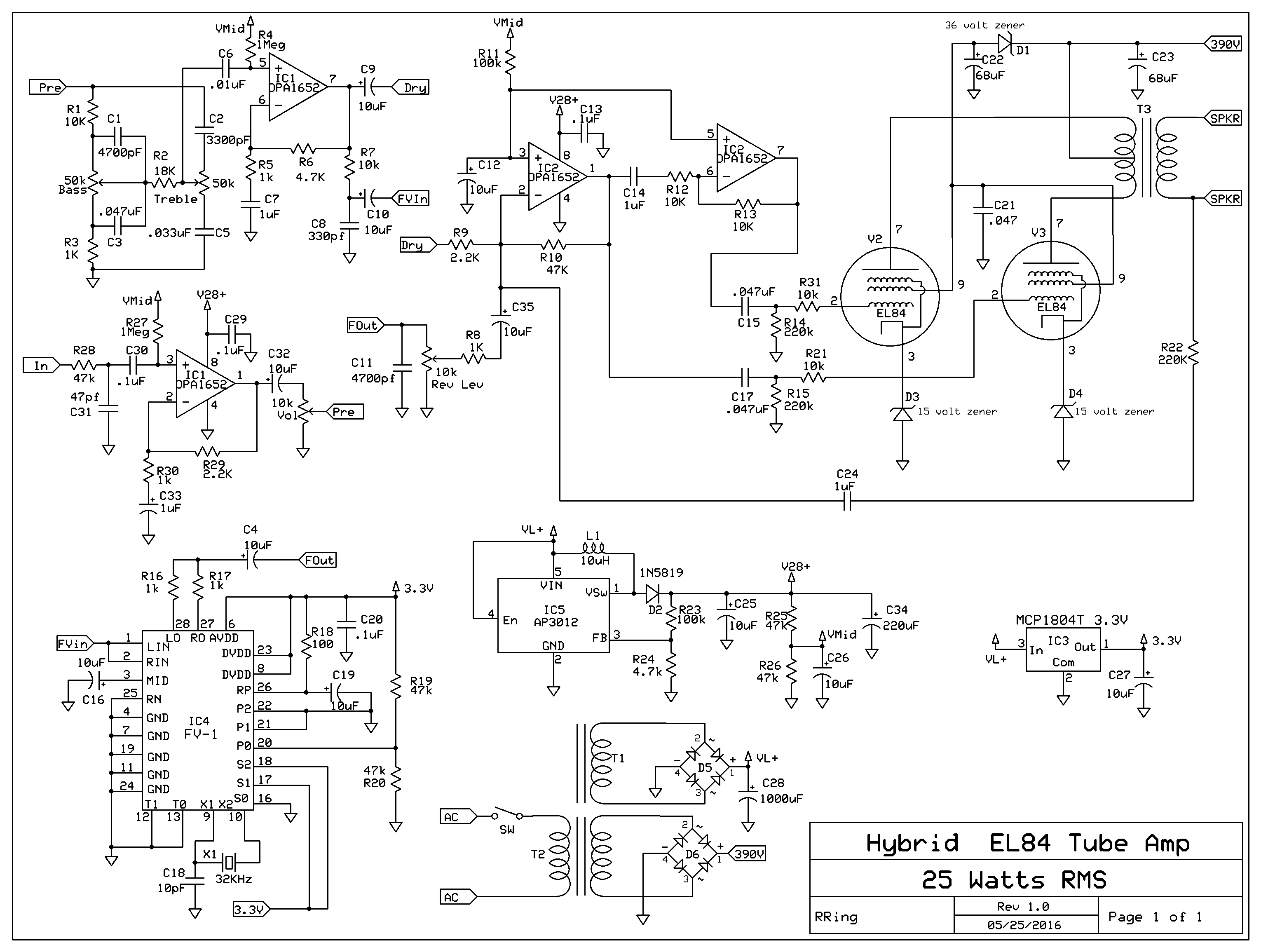
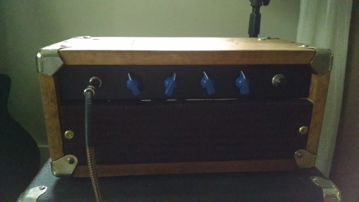
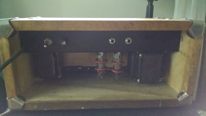
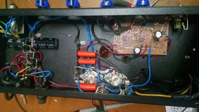
This is my new hybrid guitar tube amp which utilizes a solid-state input stage, DSP reverb, and solid-state phase splitter. Only the push pull, class AB output stage utilizes tubes, namely two EL84’s run at 390 volts with cathode bias. The bias uses two 15 volt zeners which creates a bias current of about 26mA. This requires almost 30 volts of swing on the grids to drive the amp to saturation. This is accomplished with a little switch mode boost converter that generates 29 volts to drive the phase splitter opamps. All of the solid-state circuitry runs off the AC filament supply for the tubes. The solid state portion is basically my stomp amp design( also on this blog) minus the final power amp, which is replaced with the phase splitter.
A couple notes about the design: Using zeners works great, but they can fail(haven’t had a problem yet) and typically they fail by shorting(very bad for the tubes!)..so it may be prudent to parallel with 1k ohm resistors and .1 uF caps to make them more tolerate of current or voltage spikes. I use 5 watt zeners and have yet to have one blow on me with numerous amp designs.
Also the gain distribution is not ideal. This is because of the low headroom of the FV-1 reverb IC which runs at 3.3v. This requires that there be lower gain in the first two stages than is possible – degrading noise figure somewhat. Despite this, the amp is very quiet – even with noisy un-bypassed zeners in the final bias circuit.
Front View of Amp HeadBack ViewComplete CircuitSolid State Circuit Board


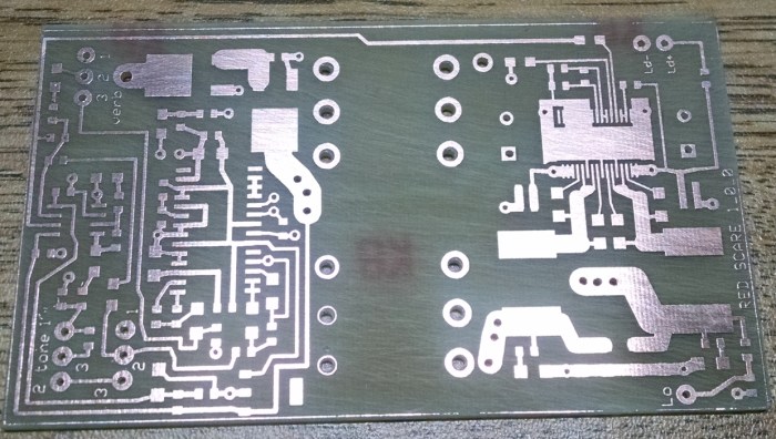 Home brew laser printer resist circuit board
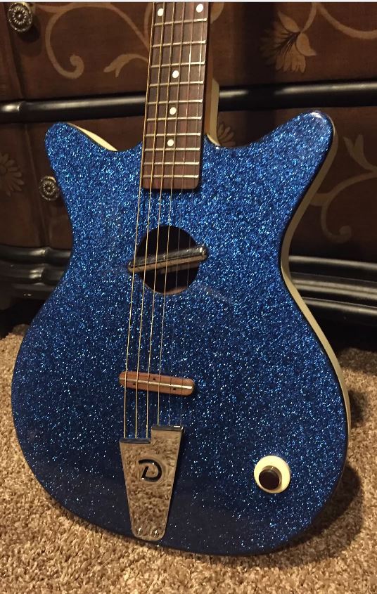


