
I finally got this thing working well. I am using a TL5001 PWM chip at 48 Khz to pulse width modulate analog switches in series with 10k resistors. The average resistance seen by the all pass filter circuits is proportional to the on time of the switches. For example is the switches are only on half the time, the average resistance is 20k instead of 10k. The advantages of this approach are that there are no critical adjustments, good dynamic range, and extremely linear resistance change in proportion to control voltage. The current draw is 25mA or so…not great but better than the 50mA I started with. The LFO is a DDS sine generator using a PIC micro controller. I will include a link to the code and a working hex file. I only use a sine wave output but the code can easily be modified to support numerous wave forms and frequency ranges. The code for this project has been modified in two ways from the DDS code described in my other blog entries. I lowered the internal clock frequency to 8 MHz from 32Mhz(saves current) and reduced the output swing of the sine wave so it did not drive the PWM chip beyond 90% duty cycle. Originally I just use the PWM directly from the PIC with no filtering but found this created noise artifacts, so I filter the output and drive a PWM chip. Typically, phaser circuits like this use high pass filter structures at the positive input, I chose to use low pass to help eliminate the switching noise from being introduced into the output. This worked well and eliminated the need for extensive filtering. The output is very clean
One thing that is very cool about this design is that it has variable sweep range instead of depth control. So the frequency range of sweep of the phasing notches can be adjusted starting at 100Hz or so all the way up to 5KHz.
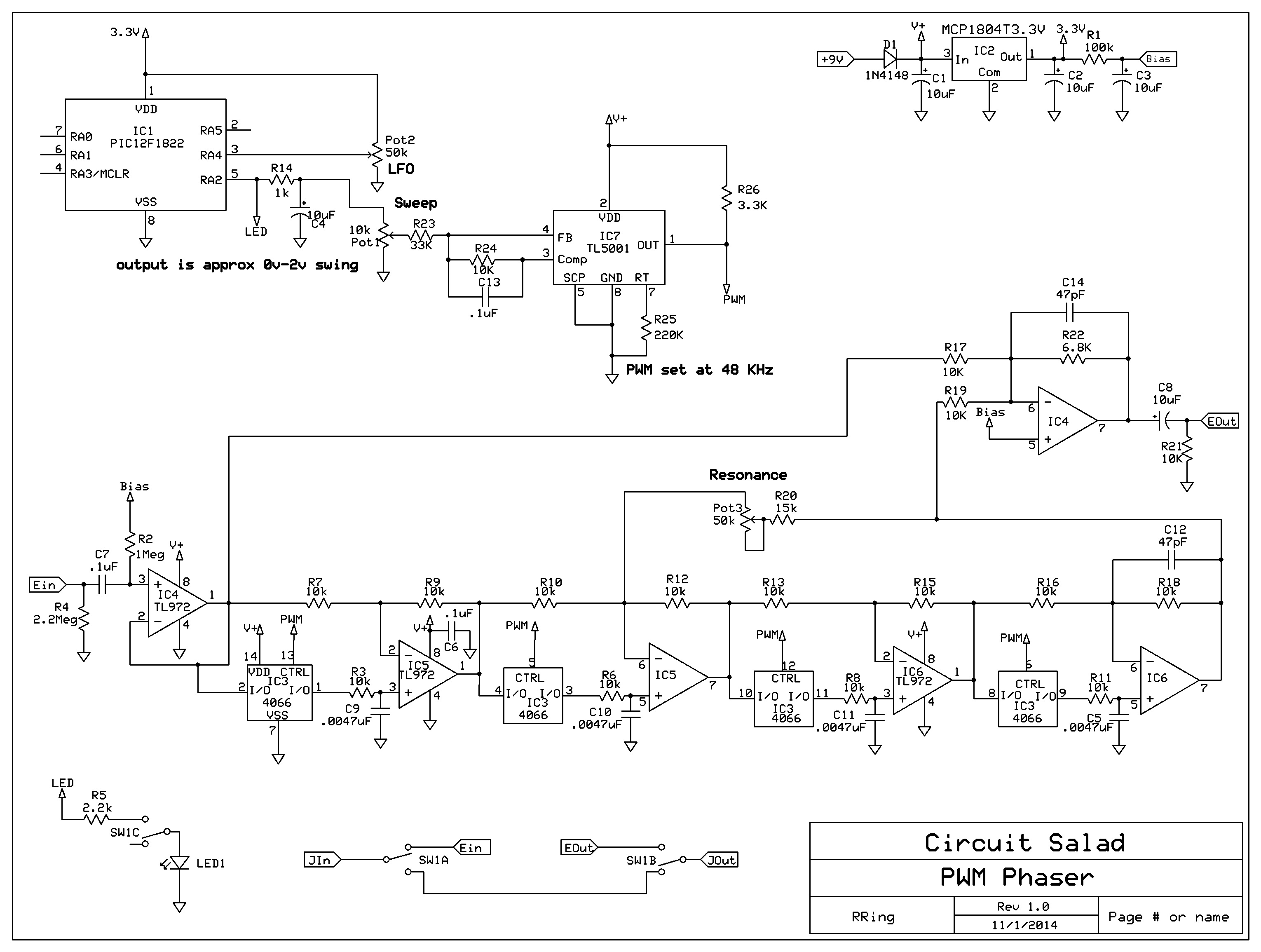
Schematic:
Demo
Link to code: https://www.adrive.com/public/mWSkFb/PWM%20phaser.zip

Looks great. Can’t wait to try it out! Can I use TL072s instead of the TL972 you used?
Going to post a demo this weekend and the code…..You can use TL072’s but I would create a half supply bias out of some 47k resistors rather than using the 3.3V that I use. This is because TL072’s are not rail to rail op amps and the half supply allows for more signal swing. You can also use any 3.3 volt regulator. A 5 volt regulator will shift the sine wave output to high and push the duty cycle too far. So use 3.3V for the PIC
I’m surprised you couldn’t use the PWM output directly from the PIC. Was the processor generating conducted EMI? A ferrite bead might help there?
such a great point! yes that’s how I started and it did work but there were periodic noise artifacts(at the peaks of the sine wave) that resulted from DDS algorithm. Perhaps I could have cleaned it up with mods to my look-up table, but I knew filtering it would work and it did.
It was not EMI.
The PWM chip works well – it allows me control the depth of the sweep very easily – which I like.
Cool, thanks. Really enjoy your site.
Couldn’t get past the “Sign up for filedropper” to dl your code. Could you email it to me? I am interested in checking out both your design concepts (use of pwm for switches, sine lookup to PWM output).
Thanks,
bartmccormick AT triad.rr.com
yes will send you a good link…sorry about the lame file dropper stuff
try this link
https://www.adrive.com/public/mWSkFb/PWM%20phaser.zip
the code was built in mikroC -which has a freeware version. This code will compile in the freeware version if you want to mod it.