
Continuing on my Stomp Amp theme; I have created a 100 watt (24V supply, 4 ohm load) guitar amplifier with FV-1 based DSP reverb and optional treble boost. It fits in a 1590b stomp box. Yes it really is a 100 watt amp!

It has Gain, a single tone control, and reverb level control. The reverb room size is set by a resistive divider(R21 , R22) and can also be made adjustable. It utilizes a TPA3116D2 class D amplifier IC which can be configured for mono or stereo output.
Click Here for Large Schematic Image:
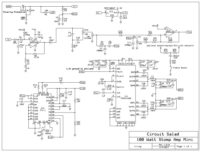
The amplifier sounds delightful. The class D topology provides greater than 90% efficiency. This eliminates the need for substantial heat sinking. The only penalty is that for guitar applications, pushing the amplifier to distortion does not sound so great. I use an overdrive pedal so I don’t care about this.
Update: I added a LED clipping circuit to make sure the input into the class D final amplifier is level limited(clips/distorts) before the final amplifier starts distorting
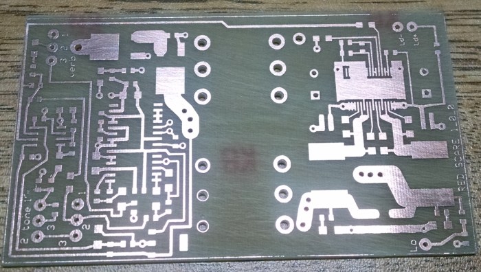 Home brew laser printer resist circuit board
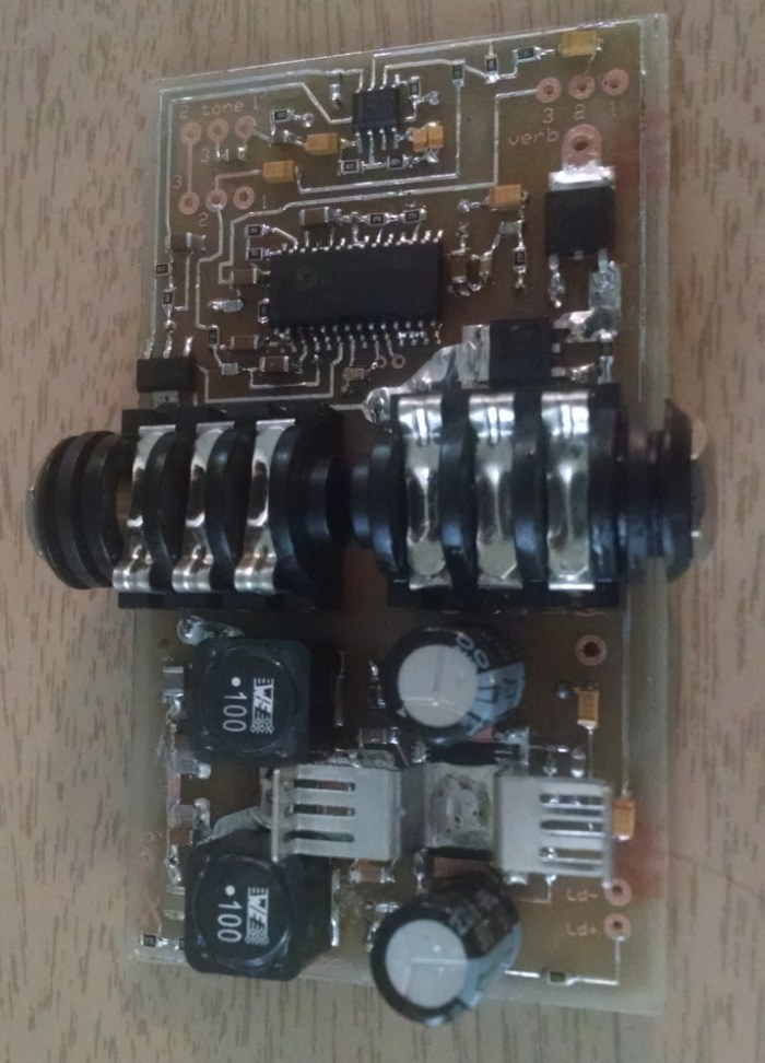
Completed Circuit Board
Link To CAD FILES: https://www.adrive.com/public/QpRQMX/RED%20SCARE.zip
The single tone control is surprisingly versatile. It alters the level and center of a MID scoop. You can get really FAT all the way to bright twang all with one control. The circuit can easily be modified to employ a more sophisticated tone stack if desired. The amplifier requires a 12-24V power supply with at least 4 amp sourcing capability. You can purchase a small lightweight switch-mode supply from Amazon for less than $20.00 that will work nicely. It is ridiculously small, lightweight, loud as hell, and sounds superb through a couple of 10″s or a single 12″ cabinet.
Quick Demo of built in Blue LED clipper limiter added to original prototype(you can see the LEDs flash as the input is clipped)

Hi Ray,
First of all, I wanted to say I am a huge fan of this blog. I got into guitar pedals and related electronics while studying RF engineering so I think it is obvious why I love it.
I want to give a try to this design in order to use it with a Tech 21 Fly Rig I got for small gigs and flying, so I don’t need the FV-1 reverb at all (maybe at some point I will try and add an fx loop, but not for the 1st iteration).
Would it be necessary to do any other modifications further to just removing the FV-1 circuit, pre and post filtering and the voltage regulator? I think that’s all, but double checking is always good.
Thanks in advance!
Best,
Adan
cool! yeah you can just remove everything at node connecting R9 and at the node at R12, the regulator and the FV1 stuff. Note: You may want a more sophisticated tone stack which easily will drop in(could use the extra room obtained by removing FV-1 in the layout), for what I do what I have is fine. Also the cap C3 has a lot of bass roll off you may prefer a 2.2 uF there or not..so be aware. Q1 is a T0-252 DPAK and needs to be any PMOS FET that is rated for 6 or more amps and 40 volts or more. You can remove this to if your not afraid of polarity issues.
Thank you very much for the notes!
I quite like the jazz tones you get out of it and my Fly Rig already has a Fender-like tone stack for further sculpting so I think I will try it like this (plus I also love simple circuits that just work well).
If I like the way the way it sounds I may work on a more advanced version that could work for both my semi-hollow and my acoustic Weissenborn with more complex features, but for now this version without the reverb looks just right for me.
I plan to work on my own layout and will of course share it here once its done (it may take a while, I am a little bit rusty on circuit design atm, it’s been a while)
Really nice clean sound you’ve got here. I would love to hear this through a distortion pedal – would you be willing to post an example of that? I just joined a rock band and have to compete with a 50 Watt Orange tube amp running through a 4×12.
yes going to post a demo off some cool stuff with the amp in a week or so
Thanks for sharing this project! Looks really cool.
I have a question; 100 W @ 4 ohms would have been perfect for me. But TI writes its actually 100 W @ 2 ohms. That would mean rather low output through a 16 ohm cab. 😦
Or do I misinterpret something?
Thanks again!
from the data sheet : 2×50W Into a 4Ω Load at 21V, 10% THD+N…..I use it in bridged mode so get 100 watts. but do the math…if we take the voltage 21volts x .707(to get rms power) we get 14.85 volts…now square this and we get 220 now divide by your Z for theoretical power 220/4 = 55 watts.
Thanks for a fast reply!
I am a noob when it comes to amplifiers so bear with me…
Looking at the data sheet, I still think it looks like 100 W @ 2 ohms in bridged mode (p10-11).
I follow your calculation, but I’m still confused. You get 55 W @ 4 ohms. Not 100 W.
I’m not trying to find errors in your post, I just want you to be right and myself proven wrong! 😁