
There is this great DSP processor chip called an FV-1 which is a dedicated audio dsp processor sandwiched between stereo 24bit ADC’s and 24bit DACs. It can be treated as a black box analog part with audio in and audio out only. With a few discretes, a crystal, and an eeprom, you can create a complete Software Defined Radio processor the size of a couple of postage stamps. The input should be I and Q baseband signals. I have also been able to demodulate AM by phase shifting the I signal at audio as the information is symmetric about the carrier. 
I have developed a complete radio design, including: the Quadrature DC receiver, and the baseband dsp processor. I have AM mode, LSB and USB. I have included bandwidth filtering for the different modes and dsp AGC limiting. I am very pleased with the performance.
The FV-1 is programmed with a free compiler provided by Spin semi…the manufacturer. The FV-1 requires an eeprom to hold the programs and you can store up 8 selectable program blocks and each can have a different program function(such as my AM, USB, LSB modes). FV-1 parts and the dev board can be purchased at:
http://www.experimentalnoize.com
The FV-1 uses a very cryptic assembly language to create digital filters and perform signal processing. The commands include multiple operations all at once, such as multiplications, additions and reading writing memory. Each command is a building block for different filter structures and operations. You can execute 128 instructions per a sample and because of the efficient command structure you can create most single order filters in two instructions. There are a number different approaches to making allpass filters. One approach only requires two instructions per a filter section and uses FV-1 delay memory. I chose to do a different filter architecture requiring more instructions and more memory. It works well but the two instruction method works fine also. The FV-1 is very well documented and there are numerous coding examples. With a little effort, reading through all the documentation, one can get up and running with FV-1 development pretty quickly
Example AM demodulator and USB demodulator code for the FV-1 (quadrature inputs)
I program the eeprom with my microchip pickit2 programmer or the FV-1 dev board. If you are going to explore algorithm design with the FV-1, I would recommend getting the FV-1 Dev board. Below is the source code and hex file for my design such that one can just program the eeprom and use what I have done, as is. Once loaded on the eeprom, the three modes AM, USB and LSB are selected by pulling to ground: Sel1, Sel2 and sel3 respectively. This code is intended for quadrature inputs to the left and right input channels and the output is on the right channel out (the schematic below combines outputs of the left and right DAC so you should probably load the output into the left DAC as well).
Link To FV-1 Hex file:
https://www.adrive.com/public/GNPAt8/SDRadioV1.hex
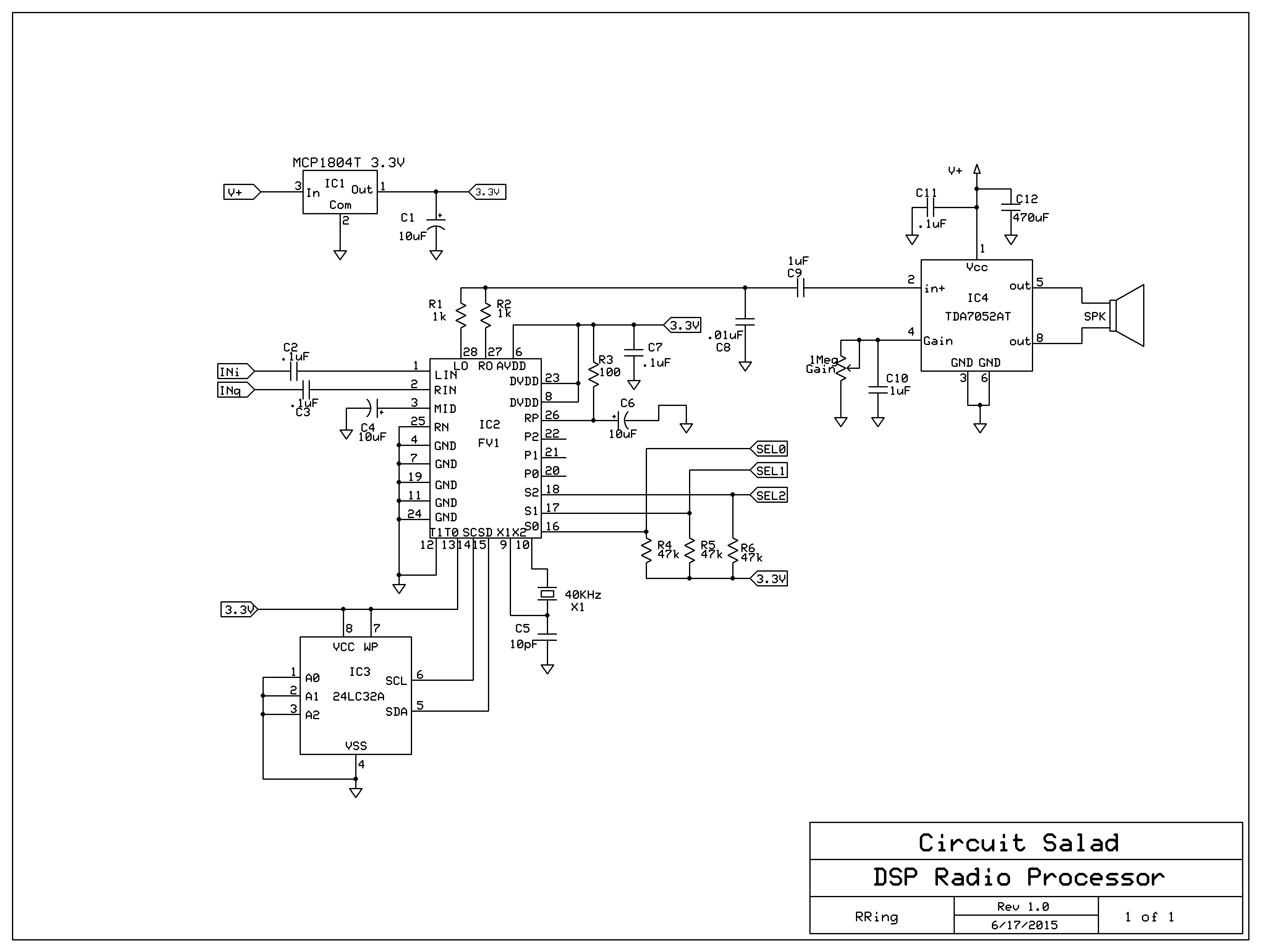
DSP processor Schematic(minor update to TDA7052AT 07/01/15)
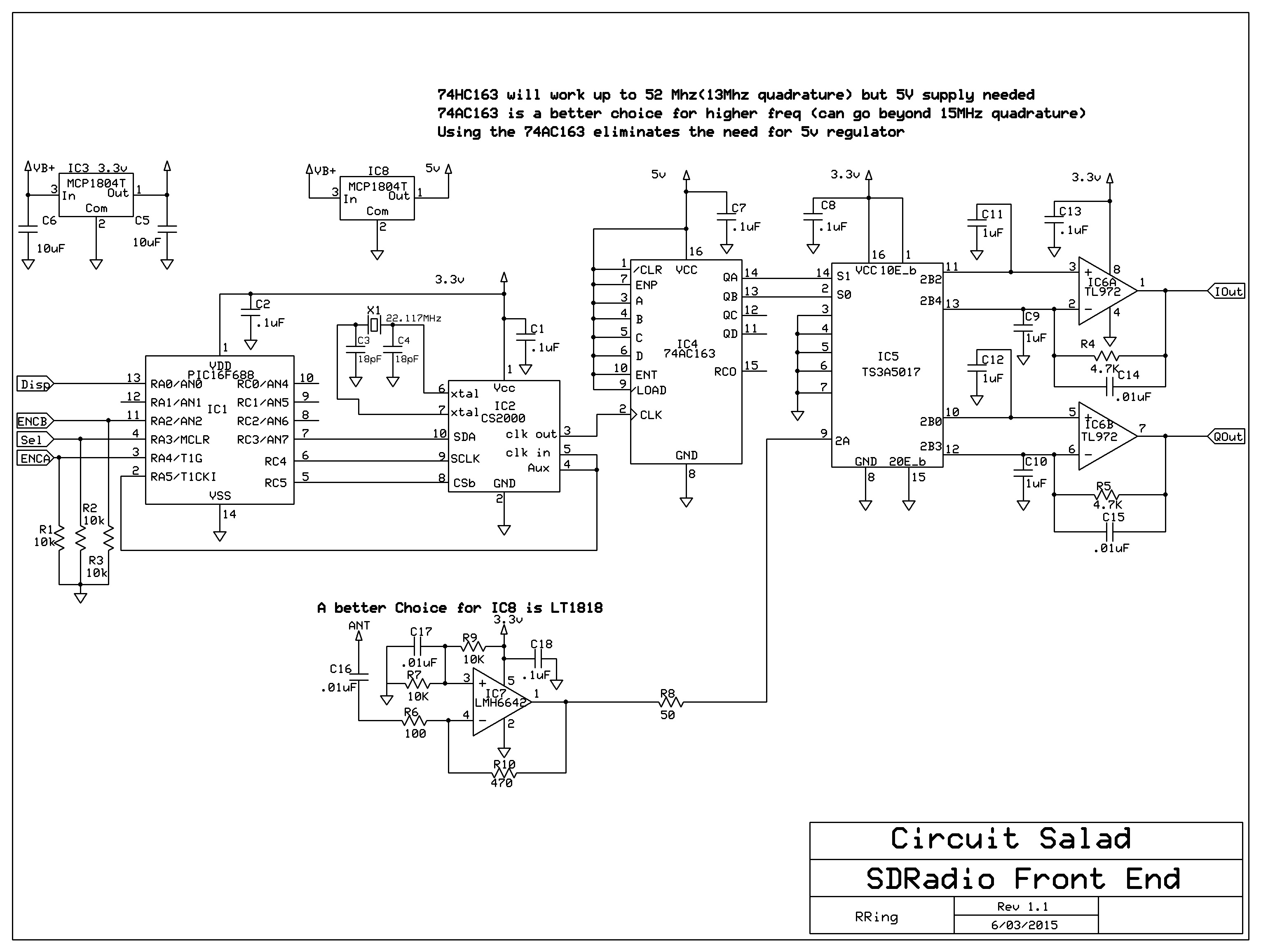
Basic Quadrature Direct Conversion radio
This is a variation of my last sampling receiver (link below)
Simplified switching mixer DC receiver uses no tuned circuits
allpass filter Calculator for IIR digital filter coefficients
Quick Demo of USB..LSB…and then AM
Demo of AM from I signal only(no quadrature)
Code for AM demodulator with single signal input, (uses two instruction allpass filter structure)

You wrote: “I and Q can be created with a hilbert transform at audio. this allows even simple non-quadrature DC receivers to be adapted for DSP baseband processing.”
How exactly do you generate I and Q at audio from the audio output of a non-quadrature DC receiver? I don’t understand the idea behind the Hilbert transform at audio.
I did a little reading about the Hilbert transform; it seems one limitation is that it only works for strong signals. For example if you had an equally-strong SSB (or CW) signal at USB and at LSB, can the Hilbert transform at audio correctly generate the I and Q channels for correct cancellation of either LSB or USB?
Yes part of the issue is me making it seem more complicated than it is. A hilbert transform is simply a 90 deg phase shift of a signal at all frequencies. We can’t achieve this ideal and so you have to design an allpass filter with a restricted bandwidth. There are number of way to do this. The best choice with the FV-1 is to create IIR type first order allpass filters cascaded just like you would in a traditional phasing ssb receiver. IIR filters are the digital equivalent of real analog circuit filters.
Steps: (I am going to post a spreadsheet calculator to assist with the steps below)
decide your frequency range(100 to 4000 Hz)
design an analog filter to meet your phase accuracy
convert into digital form with recursion coefficients(equivalent of component values in analog world)
create band limiting lowpass and highpass filters that precede you allpass chain to restrict bandwidth.
split the incoming signal into to allpass chains – and you will get quadrature signals out relative to each other which then can be AM demodulated. (EDIT 06/28/2015) You can not cancel upper or lower sidebands by creating the quadrature phase shift alone. You need to create I and Q related outputs by mixing with local oscillator signals 90 deg out of phase.
Issues: does not work quite as well as native IQ baseband because you can’t tune to frequency center (zero beat) for AM for example, also the phase error varies slightly over frequency just like an analog filter, finally there is group delay of phase which reduces signal fidelity a little – but not much.
To summarize: all I am doing is making digital versions of traditional analog allpass filters to create quadrature signals relative to each other, the digital version have the same theoretical limitations( phase error, bandwidth limitation) as the analog filters but are so easy to construct in the digital domain it is a viable approach to utilize with simple DC receivers for AM demodulation.
I am literally constructing the filters designed here:
http://www.gj3rax.com/apf.htm
on the FV-1
I need to think about this some more, but the fundamental problem, that I can’t quite see how you solve, is that the AF output of a traditional non-phasing DC receiver will have the lower and upper sidebands folded on top of each other. Are you saying that, starting with this folded AF output, with some DSP trickery you can still properly select either USB or LSB? Isn’t there always going to be some sort of image that you can’t get rid of, if you’re starting with an already-folded AF output from the non-phasing DC receiver?
This is good that you are discussing this. AM demodulation works with this approach ( I am doing it) but I think you are correct about the sideband rejection. I will review the math (just to verify). It makes sense with AM because of the relationship of the carrier to sidebands, but the unique sideband information must be lost in the conversion(ie, which is upper and which is lower). When you first were asking this question – I didn’t quite catch your main point(now I do). You definitely can not reconstruct lost information and that is the issue. I modified my post to not imply as I did before that you could reject sidebands with I only manipulated at audio. The thought experiment that comes to mind is two different cw signals on below and one above the conversion frequency by exactly the same amount, when converted to audio by a DC receiver…..they could not be separated by any filter no matter how perfect. I was able to reject the carrier with AM so I was thinking about that when I wrote about using a non-quadrature input into the dsp.
Thanks for the clarification
Just to clarify, I looked at the math and yes when you mix with an I and Q LO – you are creating unique frequency products that once shifted in phase again can be made to cancel. This will not happen by merely phase shifting at audio as this will not create the sideband products required. The AM does work however as the magnitude(envelope) information is contained in either sideband.
Thanks for catching my sloppy language. It probably would have confused people quite a bit.
You wrote: “The AM does work however as the magnitude(envelope) information is contained in either sideband.”
This is interesting and is something that I didn’t know. I like building simple receivers, especially for AM SWBC listening. I’ll have to review your approach in detail.
One DSP experiment I’ve done in the past using a PC and a non-phasing DC receiver is to tune an AM SWBC signal so that the carrier is higher than zero-beat, say at 10 kHz. Then, using DSP/SDR software on the PC, I applied a sharp-cutoff, 10-pole high pass filter that only allowed 10 kHz and above to pass. Finally I applied a downmixing operation to convert the 10 kHz to 0 kHz baseband, and could recover the audio — of course with the caveat that the image at -10 kHz and below was also audible. In other words, I made a single-conversion superhet with IF=10 kHz, ignored the image rejection from the RF-IF conversion, and did the IF-to-AF conversion (detection) in software using a 10 kHz high-pass filter as the digital IF filter. To partially solve the RF image rejection issue it is even possible to use a regenerative receiver below threshold as a Q-multiplier at RF to boost the desired sideband while leaving the undesired sideband (20 kHz below the desired signal) relatively unboosted.
Anyway, I mention this because I guess there may be some conceptual relationship between your approach and my approach.
I thought about doing that- I guess your receiver has to be very wide band(at audio) and then rely on digital filtering. The FV-1 is capable of doing all those operations…so I might mess with it. The AM demodulator I made needs to be tuned off zero beat a little – as the allpass filters can’t handle the low Frequency and there is a little carrier leakage – you can hear it in the demo I posted a little while ago. I guess it works because with the squaring, summing and taking the square root you are only left with amplitude information(the envelope) – but your approach may sound better
Regarding “The AM demodulator I made needs to be tuned off zero beat a little” — how far off zero beat?
The approach I mentioned (superhet with IF=10 kHz) requires the AM signal be tuned 10 kHz off zero-beat, but it seems like your digital I/Q AM demodulator approach can work closer to zero beat than my approach.
By the way, is your approach at all related to the software Costas-loop approach described here? http://theradioboard.com/rb/viewtopic.php?p=31598#p31598
200 Hz or so. I am just duplicating the original signal and shifting 90 deg summing the squares of the signal and calculating magnitude. I am creating a fake negative frequency but the amplitude information is the same and I am stripping away all phase information anyway so it works ok..not great. I want to experiment with the Costa loop also… I guess I need to give up sleep
Ray, thanks for the neat design with the FV-1. You’ve caused me to be seriously diverted from other stuff for hours as a result while reading up on that device, and working through the design. Great stuff!
Do you have any feel for how accurately the FV-1 carries out the Hilbert transform? Traditionally, the analog versions with multiple op-amps (like your earlier Dec 2013 design) achieve 40dB opposite sideband suppression reasonably consistently, but other factors (phase and amplitude imbalance, filter inaccuracies due to component tolerance, temperature effects, etc) tend to make it difficult to achieve anything much better, I think. Theoretically, the FV-1 digital-based design here (if the preceding RF stages were perfect) could achieve up to 60dB. My guess is, however, the FV-1 might be doing quite well (45-50dB?) but the RF stages probably still limit performance to, say, the 40 – 45dB range. Any guesses? How do you think it compares, sideband suppression-wise, with the Dec 2013 receiver?
(Of course, if you are willing to give up on sleep, this might be measured approximately using Peter Parker’s VK3YE Android phone-based audio spectrum analyser method…and who needs sleep!) 😉
Yes all of what you are speculating on is what I am trying to feel my way through. So in the first place, my code works and I have proven the basic idea…but I am sure it can be improved both by me and others!
The FV-1 is very easy to use from a hardware perspective and the software assembler is confusing but once you play with it – this is very doable also.
I think amateur radio folks will really enjoy working with this chip – you can cook up all kinds of filters..etc. Plus its a great platform for learning some basic DSP. The chip also has analog POT inputs that allow for adjustable behavior(variable notch filters ..etc)- I just thought it was best to focus on the basic functions for now
FIR type filter structures can be built…with the FV-1 and may be better performing but I understand IIR filters better coming from an analog background- so I am going to explore that approach at least for awhile
I think I am getting better than 40dB and believe 60dB should be achievable but will check with the frequensee app tonight to see what I am getting now. My DC receiver has slight imbalance with the quadrature amplitudes…I know this because my AM demodulator has just a smidge of carrier leakage(you can hear it in the demo). So I think the limiting factor of performance now is my quadrature input(to the FV-1) balance.
The filters should approach theoretical performance. The ADC’s, DAC’s, and registers are all 24 bit and I am sampling at 40Khz ( sampling rate is the crystal frequency).
About the filters…
There are enough instruction cycles to make 8 stage or more allpass filter structures. I don’t see much benefit from more than 4 or 5 though. One issue is 3db corner frequencies. When you start adding more and more stages some of the filter corner frequencies(what I use to create the digital filter coefficients) become to high in frequency and don’t appear to operate as well (to near the nyquist threshold of sampling freq maybe..not sure?). So if I get corner freq’s above 14Khz I start seeing some reduction in performance.
There are two types of IIR filter I have used with the FV-1…models of both are in my spreadsheet and they use the same calculations. One takes more memory and instructions but has better resolution and dynamic range, The other is the one shown in FV-1 documentation and uses only two instructions and one memory location but is prone to overflow..so you have to scale down the signal and then boost it back up. Seems to work fine though. My code examples use both types of filter structures. I also noticed that you need to bump up the gain for the AM demodulator because faint signals, when squared become too small and are not resolved even at 24 bit.
Its working better than my original phasing receiver and the parts count is less!
I checked with frequensee and yes I am getting 40-45 dB suppression.
That’s really impressive performance. (Sound of crowd applause) I’ve got to say thanks again for spotlighting the FV-1 with this design. I’d never have thought to look for a serious DSP device for this kind of application in the “guitar sound effects” chip sets which, I think, is really where this originally hails from if I understand correctly. Amazing.
I particularly like the 24bit resolution with everything so well integrated in the device. Are there any other integrated DSP devices like this which have this level of performance, with a similar price and in packages which can be used by the amateur like this? If so, I certainly haven’t seen them. I know the dsPIC stuff exists, for example, but they don’t seem to come close to the ease of use and performance of this device.
Those POT inputs are interesting too. Is it possible to use one for a simple 30dB AGC gain control? I’ve found this range is just good enough to reduce the worst of the impact of the signal variations on HF with basic SSB receivers. I usually add a simple four component AGC loop around the TDA7052 for this, but adding it in DSP looks nice. Not sure if the FV-1 can do that.
Yes, I agree with you over the filter length. There’s probably little to be gained by going to 4 or 5 stages, really. I’ve found it hard to hear the difference between 3 and 5 stage filters probably because my receiver had limiting factors in the RF stages (Amplitude and phase offsets, for sure)
I did hear the (very modest) carrier leakage in that video, but this was of no surprise. Many years ago (Sigh…too many) I was working on one of the earliest TMS320 DSPs doing an identical task (I/Q phase shifting at audio) for a different application, and comparing it with a four stage op-amp analog version, the “reference design”. I got the same carrier leak problem, due in my case to a tiny DC offset in the op-amp chain. Curiously, I saw exactly the same leak with the DSP system. In the analog case, I added a little trimmer to null the op-amp DC offset slightly to null out the carrier leak. In software, my DSP guru added a variable called ‘trimmer’ to do exactly the same thing. We found the right setting for ‘trimmer’ using external DIP switches, and then set it as a constant. Presto, way better result, and 100% repeatable on the 30-odd TMS320 boards we made.
Yes, I did note the 40kHz crystal / sample rate. Bit tricky to buy those sometimes but the Spin app note shows how to get that clock rate from regular crystals. I’d almost be inclined to squirt the 40kHz clock out a spare pin on the main processor if I couldn’t get a 40kHz crystal rather than go to the bother of adding more parts for a regular xtal.
Now I am utterly doomed. I’ll have to place an order for some of these devices today. There goes MY sleep…
I would break down and get the dev board. I have used the chip for guitar effects myself- which is how I found it. But it was too difficult to do quick code revs and learn the part without the convenience of the dev board.
You can of course compile and burn on an eprom, but it’s very nice just to load the code in real-time via the usb to the dev board.
Yes – I could find no other part like this and I thought the radio community would love it. Your reaction is like mine and hopefully others – that… finally, anyone who can burn an eprom; can build a respectable standalone SDR. Hopefully, myself, you and others can create some nice turnkey code that one can just load and then treat the part as an analog radio IC. You see it the way I do: that this is probably the best option for “low overhead” DSP radio development. Once you have a basic quadrature DC receiver built – you can just play and play and play with the signals using the FV-1.
In my code, I have a 24 dB limiter to keep the part from overloading and give some crude AGC. You can create a 1/x gain function which should allow for at least 40 dB of compression. I used a peak detection method- you can also use RMS detection.
I used a crystal. I think others have used clock crystals at 32Khz and up to 50 Khz. Inside a pll scales up the freq 1000x to get all the operations in between samples.
I am going to look at a digital trim as you describe to improve my carrier suppression(AM) and hopefully sideband suppression as well. I am going to build a complete radio on one board – I may use the clock from my frequency control micro also. Its probably good practice to have the numerous clk signals in such a design all synchronized anyway.
please keep in touch about your progress. I am going to keep optimizing and always like to get tips and new ideas from others
I am going to go out to the playground now; to get my daily beating and wedgie from the captain of the football team. But someday I’ll get my revenge
AGC approach sounds all I need. Sorry, missed that detail first time around. Might be just enough to prevent my ears getting blasted by the big guns 20km or so down the road (All 5MW of it. Fortunately, I’m off-axis from the 18dB (?) or so array antennas.
I’ve ordered some chips yesterday, so might have them in a month or so (Difficult getting stuff delivered here…) but that gives me time to sort out how to program the EEPROM. Probably grab out my old Ponyprog interface.
Warming up the soldering iron…
checked the amplitude offset…does not seem to be the issue. Must be a tiny phase offset in my quadrature or something of that sort. Regardless, its performing well..not sure if I can achieve 60dB sideband suppression though.
did you ever get your FV-1’s? I am interested in your progress and hope you can get a chip up and running with a program.
I’m sorry, I haven’t really done anything since contacting you. I’ve been travelling and doing some other things and frankly haven’t had time to do really anything. Hope to get to it before the first of the year, but who knows what will hold.
Harley
A pickit 2 or pickit 3 programmer will work and they can be obtained pretty cheap.
Do you think you could record a video of the non-phasing DC receiver plus your AM demodulator, when receiving music?
There seems to be a bit of the “opposite sidebands beating against together” distortion audible in your AM demodulator, but I’m wondering how objectionable it is. I have found that musical signals are the most sensitive to this and am curious how your AM demodulator (when used with a non-phasing DC receiver) sounds when tuned to music.
I’m thinking about trying to apply your AM detection approach to a regenerative receiver in the oscillating mode (i.e. a self-oscillating, non-phasing DC receiver).
I took it apart but I can physically just connect one channel of the I/Q receiver – which is nearly identical to what you described and use that. I will make some good hifi recordings and try to convey the subtle features of the sound. You are correct there is some sideband beating. This may be my all pass networks are not broadband enough and or accurate enough. It is not terrible but not perfect either. I thought about the regen idea -that is using it exclusively in homodyne mode- then you could frequency count(display frequency) and perhaps stabilize oscillating behavior over a wide range and come up with a nifty receiver. I think the best thing to do is to try and get the the allpass response as near to zero hz as possible and then tune to near zero where the beating effects will be less perceptible – especially with a regen – where IF selectivity may be narrow
Great, looking forward to the recordings.
The reason I’m pursuing this is simply to improve the selectivity of a regen when receiving AM. As we know, if adjusted under the oscillation threshold for envelope detection, the attainable selectivity depends on the Q multiplication, with the resulting selectivity curve having a sharp peak and broad skirts. This means nearby off-channel AM signals will also get detected though at reduced volume.
However if we operate the regen above threshold as a DC receiver then instead of acting as an envelope detector it acts as a heterodyne detector, more-or-less linearly translating the RF spectrum directly to audio, so that even nearby off-channel interference results in higher post-translation audio frequencies, which can be filtered out at audio.
The problem of course being that AM reception with a DC receiver (whether of the self-oscillating or separate-oscillator variety) requires zero-beating the carrier, a state that with analog VFOs cannot be maintained indefinitely due to drift.
But with your AM detector approach, you can more or less ignore the drift (only maybe touching up the tuning once in a while) and still get acceptable AM reception. And, you can filter out higher AF frequencies resulting in quite good AM selectivity.
And the hardware remains simple: just a normal regenerative receiver operated in the oscillating mode.
I’ll probably try this approach on the PC first. But I also have a TI DSP board (eZdsp C5555) that I could probably program for a standalone solution.
By the way, I’d be interested in reading more details about the math and derivation of your I-channel-only AM detector approach. Do you have any references? Or perhaps you might be motivated to write a future blog post on the subject…
I have posted a video with better audio and more tuning around zero beat – too give a sense of how well it works(not perfect) the link is: http://youtu.be/0T0Z-GrGbLE
Thanks for the latest video of the I-channel-only AM detector. This really is quite an interesting way of removing the carrier and I must admit that I lack a firm grasp on the mathematics behind your approach.
I’d like to try your approach on the PC first. My idea is to record some audio from websdr.org, configured such that both sidebands are audible and tuned off of zero beat. Then I would use that recorded audio file as the input to some other program to do the (non-real-time) AM detection on the PC using your approach.
Question: are you aware of any software on the PC that would make it easy to implement and test your AM detector approach? I think I understand your approach almost enough to implement it, but it certainly would be easier if there is some existing PC-based DSP software that will allow me to combine a few filters and test how the result sounds.
Just image what I am doing as you would see it on an oscilloscope. Take a carrier(that is am modulated)
and full wave rectify it(by squaring)…so now you have all your “humps” above zero volts on your display. Now take the original signal again and shift it 90 degrees and square and create a second set of double humps and combine the two signals(sum them). If you do this what you will see is the general amplitude waveform with the carrier imposed just slightly on the top, where the 4 humps overlap. Then take the square root of the whole sum to eliminate the squaring distortion and, in a sense, average out the remaining carrier.
This is not new to you I am sure but when you actually look at it on a scope(as I have done) you see what is happening. The squaring , shifting, summing and square root all can be seen to correspond to physical effects in the time domain
As far as computer programs, I honestly don’t have much experience. What I did, was use excel to create a wave table and the do the math, then plotted it(to see if everything made sense) also I use matlab which is great for simulating this stuff. Most people don’t have matlab – so this may be of little value to you. Matlab has a dsp toolbox add on which actually takes input from files..processes and play out your sound card – to do exactly what you want to accomplish. I don’t have this add on but wish I did!
I am very interested in the FV-1 device. I followed the link on where to order it, but I couldn’t find it. Where can I buy just one or two pieces?
Thanks,
Harley
N5BFB
http://WWW.experimentalnoize.com make sure its with a z. You can buy 1 or more through them.
I’m sorry I might have misunderstood you I think you’re saying you went to the website but you couldn’t find a way on the website to actually order? You have to send them an email requesting an invoice. It is a kind of a goofy process but they’re very easy to work with and very responsive
Hello.
I have not much experience with the DSP and I’d like to try them
I know C ++ and assembly.
in particular I’d like to do a program that I can program a low pass filter and one high pass through serial with a MCU.
thanks I hope you can give me advice on the first steps
okay are we talking about the FV-1? the actual code is very easy for such filters – The FV-1 support information on their web page is very good – my posted code shows low pass and high pass structures as well. What is not clear to me is “the serial and MCU” portion of what you said. The FV-1 uses an eeprom to hold code that it runs – so you can load up to 8 programs and use select lines to choose. If you need variable filters – the FV-1 has three control voltage inputs(use simple analog pots) which are system inputs allowing real time adjustable parameters for filters..etc.
I am not sure the purpose of the MCU/serial connection is? The FV-1 does not have a serial data input and I am not clear on what value programming the eeprom via the MCU would have?
If you are describing using a general purpose microprocessor to create your own filters in C – there is quite a bit of code out there you can use. My main advice is to select the right part for your job. You need to get a DsPic or one of the dedicated DSP processor modules because the A2D and D2A conversion hardware and processing will be greatly simplified and then you can get into the digital domain of code much quicker. You need at least a 16 bit processor.
Its not clear to me what you are trying to do so I may not be helping you at all?
thanks for help.
I wrote to you because this project is interesting, and I want to do I look like this.
Unfortunately, I’ve never tried a DSP and I did not know enough to program a EEPROM, because I thought it was like an MCU with JTAG.
so I can program a DSP with an EEPROM programmer?
my objective is to use a DSP as 0-30 MHZ band pass filter, it’s possible?
thanks a lot !
DSP works for analog processing but not in the RF range. The FV-1 for example can only work for filters up to 15KHz – that is audio processing. This of course is when we are talking about time domain signals. You can do DSP processing on data(images for example) with much greater capability because the time sampling aspect is not in play
Hi All,
It’s great to see people working with the fabulous Alesis/Wavefront DSP chips!
Some of you have asked me to resurrect my old Alesis designs from about 10 years ago, so I’ve hacked together a few of my earlier pages…..
see http://members.wideband.net.au/gzimmer/
There will be many broken links, etc, and much will be well out of date, but I hope they are of some interest.
More anon.
…….. Zim ……… VK3GJZ
Further to previous, my apologies for confusing the FV-1 chip with the Alesis AL3101.
I’m now reading the data sheet for the FV-1
Click to access FV-1.pdf
thanks ……..Zim ……… VK3GJZ
yes the designer of the FV-1 was the founder of alesis(Keith Barr) who died in 2010 I believe. I am sure the FV-1 leverages much of previous alesis design. Unfortunately when he died the design was frozen and is not advancing in anyway, fortunately they still make them.
Do you have artwork files (CAD, etc) for the PCB shown in this article?
Joe
yes its test stuff and modular but I will post what I have. Give me a couple of days
here is a download to schematics,PCBs, firmware(for radio)
https://www.adrive.com/public/EDzv7J/SDR_data.zip
Ray
Thanks! What CAD package are these done in?
Joe
you have two choices, the free express pcb tool or the copper connection which is also free
you have two choices you the free express pcb tool or copper connection…which is also free
OK, thanks.
Another question…where did you purchase the FV1 chip and how much did it cost?
I think all that info is in my blog post. The company is “experimental noize” ( with a Z) and $10.00 per 1
I just threw together some code to get it to work..with better filter design..should make an excellent receiver
Hi Ray.
I just read rhe post twice again and didn’t find any reference to distributor or price, but thanks for supplying it.
I’ll look forward to you posting the PCB files.
Joe
yes okay…I reference the chip in a number of posts…I will add that info to that post as well. Its obviously relevant
SDR_Radio_v1.hex file for use Tuning Fork Crystal 40 KHz Cylinder ??? correct ???
beacuse Datasheet 32.768 KHz info.
Please return info..
73 best reagards..
I designed the filter coefficients for 40Khz. the FV-1 can use any frequency up to 65 KHz
for info ,many thanks
Hello friend, my assembly working SDRadioV1.hex well good.little problem volume control FV1 chip.
your second projects pin 20 gain contol.I am try compiled not hex file.please send me si5351 projects new version working for FV-1 hex code. I am try selector pins hardware switched change. best reagards..73
So you want my newest FV-1 compiled Hex for my new version of the SDR because it provides gain control? is that what you are saying?
yes gain adjust LSB and USB decoded Hex dump file need..
I added the complete hex file to the tech data link that is in my most recent SDR post: the three FV-1 select lines(0-7) are selected as follows: 0 ->AM ; 2-> LSB; 4 >USB
many thank’s Ray…