Some Possible Value Mods for the Simple Opto Compressor

There is another builder/designer Jon who has experimented with a number of my compressor circuits. He recommends a lower value for R1 of around 22k instead of the 100k in the schematic. This will lower the max compression a little, but will help with stray capacitance roll-off of high end.  It should work fine.  It will load the guitar pickups a little with heavy compression. Also the diode peak detector is biased in a more linear range by changing R8 and R6  from 470k to 47k and C7 from 1uF to 10uF. I think these values will work a little better.

Over my choices are:  100K for R1,  47K for R6 and 10uF for C7

More Amp Updates – Revised schematic – Very minor mod to PCB – this should be it!

I have one guitar that belts out a huge signal from the neck pickup. I was able to  make the first stage just start to distort. To correct this,  I have changed R5 to 1K and R3 to 4.7k  also I have un- bootstrapped R4 and directly connected to ground. I thought the bootstrapping was a good idea – I must have eaten too many Twinkies that day.  C30 and R29 are still optional but could be used to give treble boost or hi/lo gain boost etc.

If you have already obtained the earlier board rev, you need to cut the trace from the emitter of Q1  going to R4 and ground that side of R4 to the ground plane.

I am posted a link to the new board rev here and obsoleting the schematic and layout in the old post. All I did was eliminate this trace and add a couple of wire connection pads to allow making R29 a POT for variable gain. If you have the old board it will work just fine – with the mod described above.

Updated Schematic:

https://circuitsalad.com/wp-content/uploads/2013/03/portaamprev1-1-1.gif

Updated Layout:

http://www.fileswap.com/dl/EDZsklrqcT/

Couple other minor notes: C16 may need to be increased to 22pF or so if you have a sluggish crystal –  had one out of five that needed the bigger cap. Also with the mods above you may find that C21 should be increased to .22uF or more depending on the range and level of treble boost desired.

Portable Battery Amp – thru-hole version Schematic and layout link

Took me awhile, but here is the new design. It’s very similar to my original design https://circuitsalad.com/2012/08/31/20-watt-battery-powered-guitar-amplifier-circuit/. I am still  using the FV-1 DSP chip for reverb which sounds great – but you can leave it out. I moved the position of the volume control after the first preamp and this helps the loading of the guitar and improves the noise figure a bit. I added a presence control in the negative feedback loop between the final amp the driver stage – this really adds some nice high end sizzle – if that’s your thing. The topology including: the fender type tone stack and the output feedback from the speaker back to the driver is much like a classic tube amp and to my ear has a nice sound. One big change was the replacement of the JFET preamp stages with Darlington transistors. You can make your own out of two generic npn’s or use another than the one I specified. Alternatively, you can use a Mosfet like a 2N7000. This may require some adjustment of the biasing. The reason I changed this was that the JFET biasing from device to device was fussy and so my schematic biasing values did not always work out correctly. The Darlington biases very consistently and I love the sound. Another reason was just for the fun of it ( don’t usually use the Darlington much).

Lots of options to adjust the tone stack, treble boost  in the first stage, the feedback loop on the final and the reverb tone shaping. I am sure if someone puts some effort into it, they can dial in some further improvements. The FV-1 has multiple selectable effect programs. The last reverb program is hard wired( all three pins pulled high) but these traces are on the bottom and can easily be cut. There are ground connections right next to these pins so that  one can cut a given trace and connect the pin to ground,  changing the program.  The FV-1 has a good data sheet and explains this in more detail.

The final amp is the TDA7396 which is capable of cranking out up to 65 watts(2 ohm speaker) – it is easy to work with and current in production. It works well with 10 – 16 volts and in this design is intended to be used with a generic SLA 12 volt battery or  a 12-14 volt @ 3 amp supply.

There are only a few surface mount parts, the PMOS FET I use for polarity protection, the FV-1 and the 3.3volt regulator. The polarity protection can be left out or a rectifier can be used instead. Other 3.3v regulators can  be used also. If you leave off the FV-1 – you don’t need the regulator at all or the two reverb controls, and it will just work as is.

the controls on the AMP are: Volume, Treble, Bass, Reverb room size, Reverb level and Presence.

For the speaker I used a $22 Jensen 8″ MOD 4 ohm. I highly recommend this speaker – its cheap and sounds just right for this amp.

Go here for the correct schematic and layout:

http://www.circuitsalad.com/2013/03/27/more-amp-updates/

Schematic: 

https://circuitsalad.com/wp-content/uploads/2013/03/portaamp31.gif   (updated in later post – do not use)

Link to the expresspcb layout:

http://www.fileswap.com/dl/mp258DXnm/ (updated in later post – do not use)

Prototype Images (the posted board artwork is slightly different than what is in this image because of corrected errors):

IMG_5307

IMG_5305

IMG_5313

New Amp Completed

IMG_5318

New Amp Showing Back

IMG_5319

14.4V Drill Battery Power Pack

Sound Clips: (coming this week)

The OPTO compressor revisited simple and works well

I have been playing with all sorts compressor ideas and the circuit below is about the simplest thing I have come up with that works well. It uses just a handful of parts and needs no critical adjustments. It has fast attack and slow decay – which I find the most useful  for guitar.

here is the schematic:

https://circuitsalad.com/wp-content/uploads/2013/03/simple-opto-comp1.gif

Additional notes here:

https://circuitsalad.com/2013/03/30/some-possible-value-mods-for-the-simple-opto-compressor/


link to ExpressPCB layout:

http://www.fileswap.com/dl/PFYBP3Gwp4/

It utilizes a number of features from my other designs and I have also integrated some suggestions from other designers (like using a darlington for the amp stage).

This design has the folowing features:

a  H11F1m OPTO FET variable resistor to control gain.

a darlington transistor as a shunt/shunt feedback amplifier. The biasing and feedback (from the collector to base) is critical to the design. The reason is that it keeps the voltage across the OPTO FET very low so as to keep it’s behavior linear. With out this feedback – there can be distortion.

LM358 beef stew op amp as a compensated diode peak detector and as a current mode amplifier the drive the H11F1m OPTO FET variable resistor.

The LED indicator is tied to the compression feedback loop and indicates compression level with variable brightness.

Demo  comming soon.

Thru Hole Version of Improved PT2399 Delay PCB Available Now

Check out earlier posts to learn more about this device and see and hear demos. I can’t say enough about how happy I am with this design! The only surface mount part is the MAX 7401 IC which is a SOIC8 and easy to solder.

Go to the link below to download the express pcb file. You can use this, modify it and have the board produced quickly by www.expresspcb.com at a reasonable cost. Check out there site for more detail if you are not familiar with the service

link to zip file with schematic and layout info:

https://www.adrive.com/public/PeAeX9/PT2399%20delay%20files.zip

Here is a picture of the layout to scale:

analog_delay_PCBThe Board Layout can easily be altered add PCB Jacks, or resize, etc. Currently it is sized to fit in a 1590B type stomp box.

Simple Mosfet Compressor MODs

Another designer tried my mosfet compressor using a darlington pair as the gain stage  device Q1. He described some improvements in performance – so I tried this as well. I love it! Using a darlington such as a MPSA14 (or a homemade one) is a drop in replacement for the MOSFET Q1. It gives a little more gain and reduces noise in the control loop slightly (allowing more freedom in changing and or eliminating C7, c8, C9). I definitely can reccomend it.

New Schematic:

https://circuitsalad.com/wp-content/uploads/2012/11/mosfet-compressor1.gif

Board layout and final schematic for Mosfet Compressor

Here is a link to the expresspcb layout for this compressor. If you are not familiar with expresspcb  look it up. They provide a layout tool and it is very easy to use and you can get boards  manufactured for $60.00 and get them in less than a week. This particular board layout uses PCB mounted jacks that are arranged to exactly fit in 1590B type stomp box. You can easily remove these jack footprints from the layout and shrink the board, modify, etc.

http://www.fileswap.com/dl/JHKVxTjROZ/

Here is the “final schematic” that matches the layout.  This version is using the LM358.

Note: using 22k for R6, 270pf for c8 and 270pf for c7 will give a faster attack – which might be preferable.

https://circuitsalad.com/wp-content/uploads/2012/11/mosfet-compressor1.gif

Video Demo of the compressor:

http://www.youtube.com/watch?feature=player_detailpage&v=iEcPEYB0Wao

New compressor design – updated 10/28/12

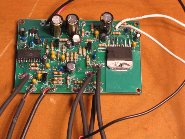
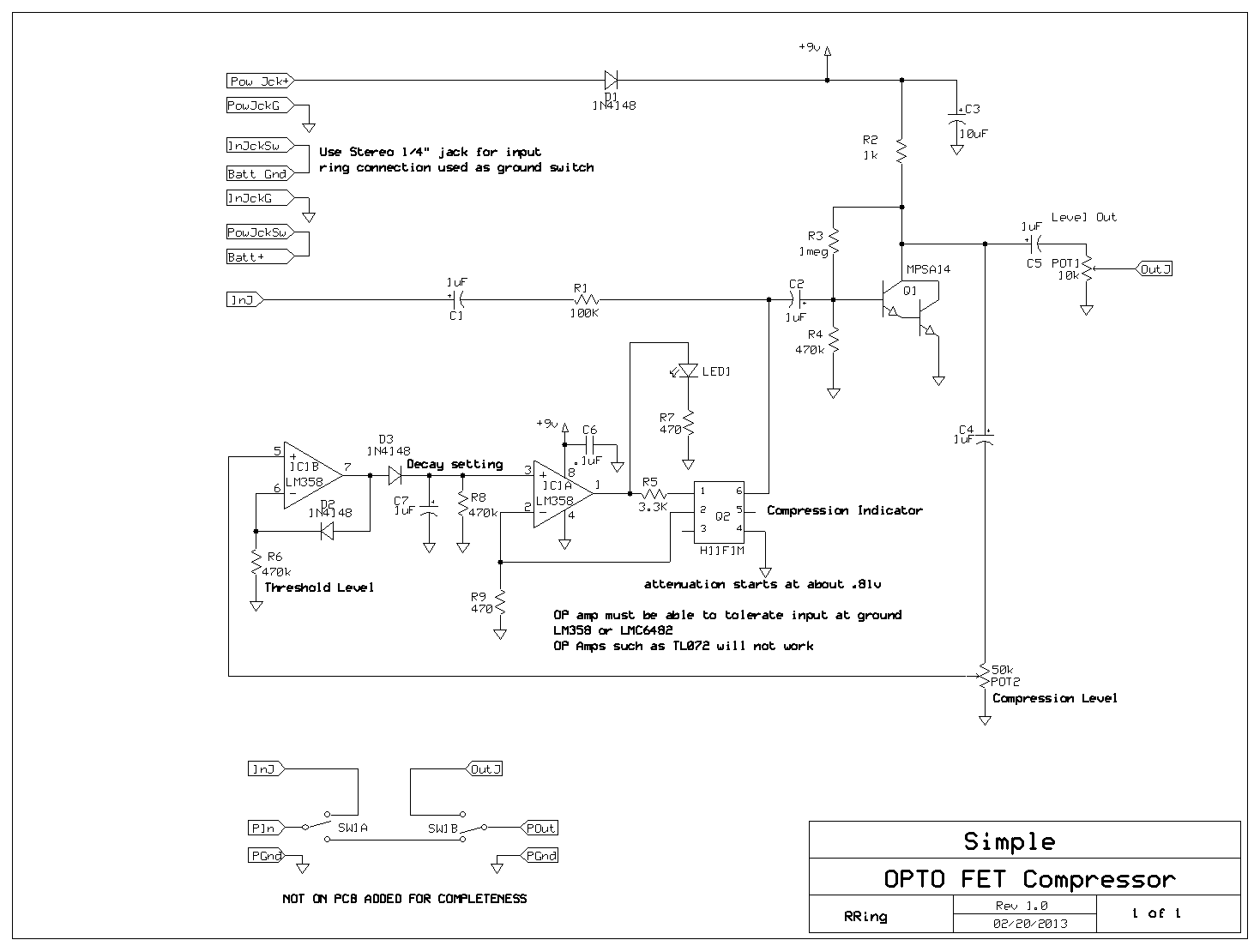
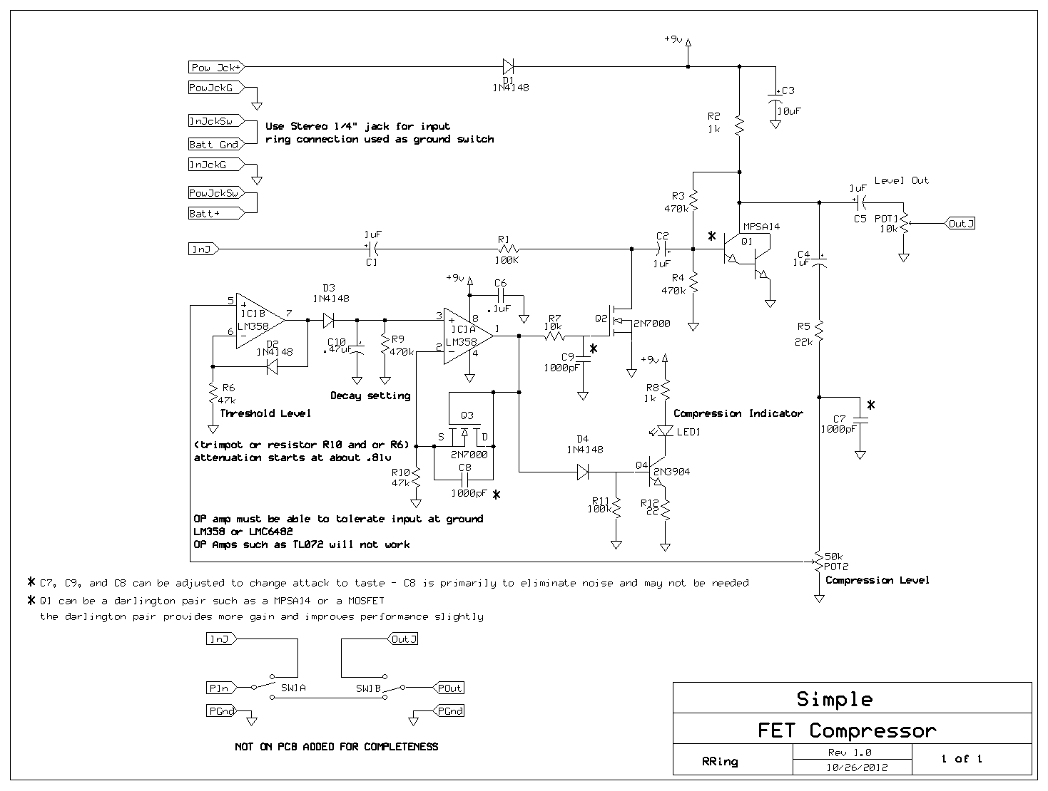
Here is the schematic for a new compressor design, which has very small parts count but flexibility in threshold, attack and decay settings.

The design uses generic NMOS FETS such as the BS170 or 2N7000 and the only critical part is the one dual op amp which needs to tolerate voltage swing at or  below ground. I am using a LMC6482 but others will work. Another designer built my original compressor using the LM358 and after looking at the data sheet believe it will work here as well.

I am using a 2N7000 as a voltage controlled resistor and it works well but cannot tolerate a drain to source voltage of even 100mV. I solve this by using shunt feedback from the drain to gate in the amplifier stage. This creates a cancelling signal at the input node, proportional to the gain, which reduces the net voltage seen across the 2N7000 down to tens of mV(with a 2 volt input).

The 2N7000 has turn on voltage starting at about .8 volts. The circuit has a 2N7000 configured as a supply independent voltage reference which provides the bias for the voltage controlled resistor. This reference is adjustable and can be used to set a variable threshold of compression or fixed at whatever threshold desired.

This design also uses a simple op amp peak detector which would be normally used in a sample and hold circuit. A bleeder resistor is added to create a decay response as desired. Because a peak detector such as this tracks instantaneous level changes – it needs to have it’s very abrupt shifting of output level smoothed out to eliminate sharp noisy spikes as the amplitude changes rapidly. This is achieved with a simple low pass integrator on the input of the 2N7000 voltage controlled resistor. This smoothing filter sets the attack. The peak detector can use just about any diode. I am using an LED which lights up and varies in intensity with respect to the amount of compression. This provides a visual indicator of how much compression is occurring. No adjustments are required to use different diodes.

In all, you can adjust the attack, decay, threshold, compression level (from 1:1 to greater than 3:1), and output level with this design, and it only uses three mosfets and one op amp.

Check out the schematic here: Consider this obsolete….. look below for improved design

https://circuitsalad.com/wp-content/uploads/2012/10/simple-compressor.gif

Update: I am changing the design of this compressor somewhat to eliminate some noise caused by the closed loop peak detector. The updated circuit is below. It uses an open loop compensated  peak detector instead of the closed loop type. Also I separated out the compression level indicator – which really works well. It has the benefit of giving visual indication of threshold adjustments which can be set by R6 and R10.

I don’t need the final buffer either because the threshold settings and control loop gain allow the output match input level at max compression.  Many of the component values can be adjusted so expect to play around with some values. Currently, I am using : R6(100k), R9(1Meg), R10(10k), C10(.1uF). Changing R9 and C10(smaller cap and larger resisitor) lets the op amp slew a little faster – no big deal. If I have any big revelations that something is better – I will post it!

New Schematic:

https://circuitsalad.com/wp-content/uploads/2012/11/mosfet-compressor1.gif