
I am going to be posting any tweaks, component changes and firmware/circuit mods here on this page.
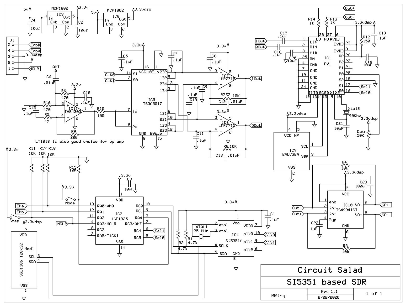
02/02/2020: Changed the RF input buffer to a better performing amplifier with another option annotated as well. Also I changed some resistor values in this gain stage to improve performance.
02/07/2020: Oops the integrating capacitors on the switching detector were shown as 1uF…it has been changed to the correct value of .1uF
02/07/2020: Updating the download link with the new schematic and an improved AM demodulator for the FV-1.
Coming soon: New code for FV-1 based on 48Khz sampling…plus new schematic/layout utilizing the leftover SI5351 output as The FV-1 clk instead of a 40KHz xtal.
Newest Schematic here:

Hello Ray. First of all thanks for sharing the design and schematics.
I am interested in building this SDR and have already sourced the components.
I’m comfortable following through the instructions you’ve provided so far to build this device, but I don’t have previous experience designing or changing electronics designs.
I wanted to ask you and make sure before printing the PCB: are your Gerber files included in the zip file, up-to-date?
And would you recommend waiting for the “Coming soon” changes, or I should already start building based on the current design? I would wait by all means, if you’re going to release updates to the design.
Thanks and best regards
Mehdi
Everything is up to date. I have had some minor clerical issues that others have pointed out. For example, I had 4303 instead of 4304 for the RF input op amp part number. Importantly the PCB is correct and the software all works. Perhaps as you proceed there may be something that seems confusing or unclear but I have built a couple units from the ground up and they worked perfectly. Fortunately, much of the behavior is driven by software that is easily modified, so you will be able to tweak the design if desired. I you have any questions as you proceed I am happy to assist.
Hi Ray
I just noticed that the display is being powered from a separate regulator. Is that because it would cause noise if connected the other regulator used to power the rest of the circuit? I’ve seen comments about using oleds in RF circuits causing noise.
Cheers, Ian
Yes the OLED creates some noise when you send it data. The two regulators are to isolate the high current audio and DSP from the RF.
Hello Ray,
I have built a board with the 16F1825 mcu.
Do you have any updated firmware newer than Firmware-rev1_16F?
I have noticed that on your revisited design with 18F you have improved the Si5351 SetFrequency and setupPLL.
My frequency range of interest is 3.5 to 29.7 MHz.
Thanks a lot in advance,
Konstantinos
I will look and see where I left that