
I decided to try using a small wide band E field type antenna with my newest receiver design…the Mini SDR and the results have been gratifying. There many useful articles describing this type of antenna; so I won’t go into much detail about how it works. More or less it functions as a capacitive E field probe and therefore is very sensitive to EMI. However, if placed outside away from house wiring and provided with a modest local ground reference..the antenna is a good performer. The classic circuit uses a JFET source follower and a BJT follower stage to provide impedance transformation of the Hi Z capacitive terminal to a 50 ohm Z drive for transmission line. This circuit works fine but has some drawback, namely requiring 65mA of current and having a somewhat large input capacitance, which reduces performance with frequency. I decided to use a wide bandwidth op amp to simplify the circuit, reduce current, and provide a little voltage gain. The op amp I chose was one I have used before for RF amplification..the LT1818. When choosing an op amp for such an application..there are a few important criteria to focus on:
1. current noise: Unlike low impedance topologies where voltage noise and resistor thermal noise will dominate, having a Hi Z input will make the current noise the dominant source of amplifier noise.
2. Bandwidth: you need a wide bandwidth on the order of hundreds of MHz or more to provide the required frequency response up to 30Mhz. This is especially true for voltage feedback op amps, where the phase shift compensation rapidly reduces performance over frequency.
3. Slew rate: You want the largest slew rate you can get to reduce distortion and IMD products.
4. Input bias current/ input Z/ input capacitance: You need low input capacitance so as to not to create a lossy divider with the antenna terminal. You want low input bias current and high input Z to not load down the terminal. If the input bias current is too high , then you need a low value bias resistor which loads the terminal.
5. Low output impedance: To drive 50 ohm Z and minimize distortion.
The LT1818 has excellent specs with regard to all of these criteria. It can operate on 3v-12v and requires only 9mA of current to operate. The Amplifier will operate from VLF to beyond 30Mhz with no change in performance.
Schematic:

The antenna is powered via a power splitter connected between the receiver and antenna. This is the purpose of L1 to isolate the DC power from the RF output from the antenna.
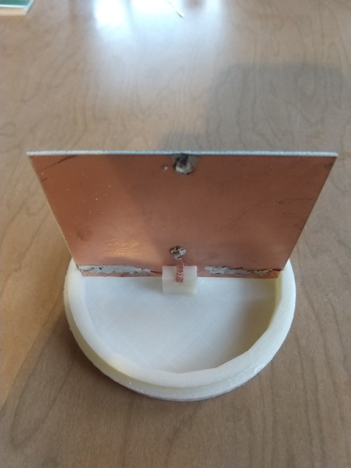
I 3D printed antenna capsule from HIPS, which is a low RF loss material and used a 3″ square of PC board to create the capacitive antenna terminal. The printing was done at 50% density so it’s a very light, low dielectric loss enclosure.
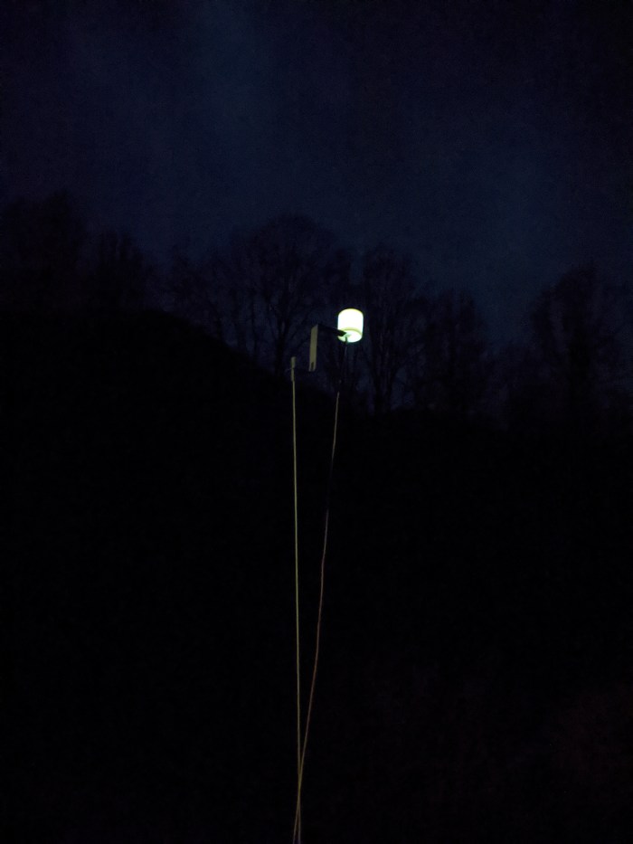
Installed Antenna(with LED illumination)
Antenna Element

Complete 4″ x 1-1/2 inch antenna

Amplifier Circuit

Antenna Terminal
Efield Antenna Demo:

“I 3D printed antenna capsule from HIPS, which is a low RF loss material and lined it with copper foil to create the capacitive antenna terminal.”
I’m not understanding part of this, sorry. “The antenna can was 3D printed from polystyrene” Got it, but, “…and lined it with copper foil to create the capacitive antenna terminal.” totally loses me. What is lined what with copper foil, the cavity of the can? But the night shot of the antenna powered up shows the sides and bottom of the can allowing light through. Any copper foil would block light. Are you talking about the FR-4 copper clad antenna card? I worry that I’m missing some novel part of a design change from a typical PA0RDT. A 60-second show and tell video would do wonders for clarification of the physical build.
Uhg !!! sorry about the confusion…yes I originally used foil but changed it to PC board so I could illuminate it and forgot to revise the text. The foil works the same and you can get more capacitive surface area in a smaller space but I like things that glow…so style wins over size.
Thanks for clearing that up. I’ll place a Mouser order and bring in the op amp. BTW, the schematic calls it out as LTC1818, discovered it’s LT1818 during the look-up. All the caps can just be MLCC X7R ceramic, correct? Power supply unit and grounding same as with the typical PA0RDT?
“I like things that glow”
I hear you. Consider a flicker circuit to simulate a candle inside. Bed Bath and Beyond has cheap electronic candles that the circuit board can be removed from.
Yes I don’t think anything is to critical with the caps except self inductance…voltage across them is low and the values are not that critical. Yes..I need to review part numbers better..I deal with so many different components all mixed up between my professional and hobby work…I need to be careful to get the nomenclature correct. Yes I would be afraid to include any circuit that could generate EMI! yes that is a great op amp for RF amplifier applications of all sorts including driver circuits for xmit amps
[…] Ring at Circuit Salad posts the design and build of a simple, low current mini-whip […]
Hello,
Thank you very much for sharing your desing, I already have all the required components to build one but I still have a doubt.
Is the solder blob on the top of the pcb a via to the other side of the copper or is it single sided?
Thank you.
It is a double sided board but a single sided will work fine..I wanted the two sides to act as one…so I bonded them.
What a great and novel design!
It’s one these designs that instantly trigger the “why did I not think of that” as soon as you see it.
I built a few and compared it to a Miniwhip design.
This design measured better in IP3 performance.
Here is the data from my measurements when operated at 12.0V
P1dB =18dBm from 3.5MHz to 28MHz. At 50Mhz it dropped slightly to 16dBm
Output IP3 in dbm was as follows:
3.5MHz =36
7MHz =35
14MHz =37
28MHz =28
50MHz =20
Gain is -1dB over it’s entire range.
The lower -3dB point is at 40kHz and the higher is up in the VHF range.
If you want to limit range to HF you can add a 100pF capacitor across R1 and insert a 39nH inductor in series with R5.
This will give you a low pass filter that will help avoid over driving the amp if you operate nearby VHF transmitters.
-3dB will then be at 35MHz
-6dB at 64MHz
-12dB at 96MHz
-24dB at 144MHz
73 from Sweden and thank you for sharing this great design.
//Harry – SM7PNV
Hey There! Thanks for giving this a try and doing some tests. Layout can be critical for stability when using op amps such as these, did you have any trouble with the circuit oscillating? I appreciate you telling about your experiments.
Hi, It’s been a while am looking to this schematics thinking to implement it.
Could you please explain, why you need to ground the antenna through R4 and R7, what is the point of connecting it to the +DC through R3.
Another question: it looks like it has the gain of the order of 2, why 2? wouldn’t you want to have a tunable gain? (a resistor that you can change the value)
Thank you in advance, Valentin
You need to bias the amplifier to 1/2 supply so the output can swing between the supply rails… You cannot have too much gain for a number of reasons; you want to have large dynamic range in the antenna. You don’t want to overload the receiver which probably has quite a bit of gain itself,. You want to keep the resistor values as low as possible so they don’t generate thermal noise…. Increasing gain doesn’t make the signal to noise ratio any better and that’s the primary objective. Finally, with that large capacitive terminal on the input, the amplifier will have a tendency to oscillate and increasing the gain will make that happen, so it’s not a practical implementation for stability reasons.