
Go here for the most up to date circuit /firmware mods: Design Updates
This is a revised version of my FV-1 based SDR. I replaced the CS2100 clk generator with the Si5351 clk generator. The Si5351 has some advantages over the CS2100, namely you can generate quadrature clks directly. This simplifies the hardware design and improves the quadrature accuracy. The sideband rejection in LSB/USB modes is impressive..somewhere around 60 db as best I can measure. The DSP processing is accomplished by the use of a FV-1 audio processor. The device makes the base band signal processing a snap. It requires some code to be loaded on a EEprom but the circuitry is simple and allows for up to 8 selectable programs. I created three: AM/USB/LSB . The FV-1 provides for three analog POT inputs to control any parameters you choose. Gain, variable filter bandwidth and depth, AGC are some examples of adjustable parameters if you desire. I kept it simple and created fixed band pass filters to taste. I did use one of the controls for AF gain. The design has no tuned circuits or band pass filters but they could easily be added. It works just fine without them. Occasionally, I come across a ghost signal from harmonic mixing, when tuning, but not enough to matter. The design uses an OLED display and a rotary encoder for tuning. The frequency coverage is from 2.7 Mhz to 25Mhz. The bottom limit is created by the inability of the Si5351 to support quadrature below this frequency. Although I have improved my DSP programs for the FV-1 and have developed new display drivers and the new code for the Si5351, useful detail about using the Fv-1 can be found in my original design from a few years ago: https://circuitsalad.com/2015/06/19/comming-soon-stand-alone-software-defined-radio-baseband-demodulator-no-computer-required/
Schematic: Updated 05/17/2020
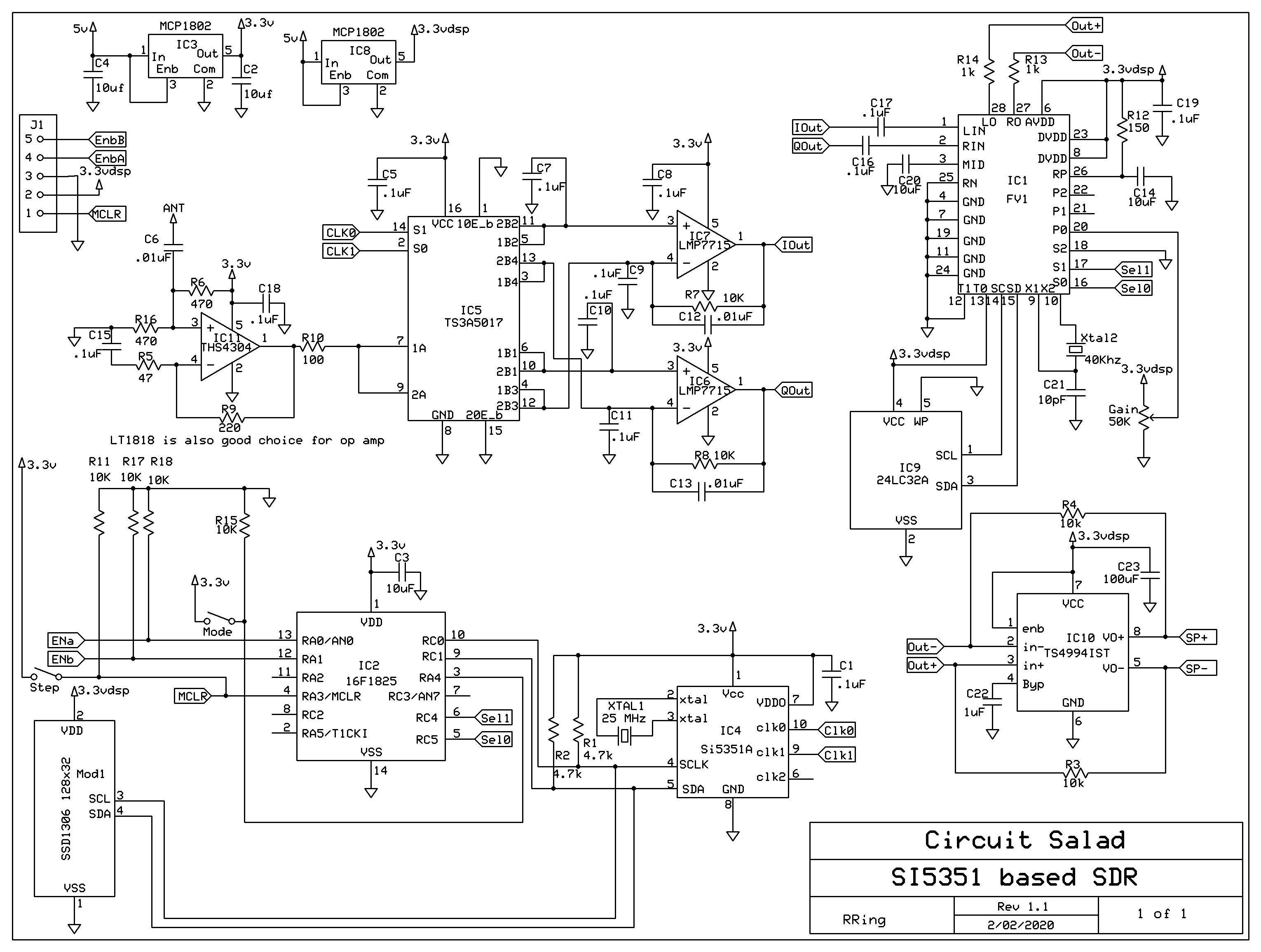
The design uses a LT1818 or THS4304 low noise op amp as an RF input with gain. It provides a constant and reliable resistive Rf termination for the sampling detector. This allows for random antennas to be used without adversely affecting the input termination to the detector. All the code to operate the main processor(display/clk generator/tuning, band select and receive mode) was written in MikroC which is a C compiler for PIC and AVR processors. The generation of quadrature signals out of the Si5351 is not difficult to implement once you know how but..figuring that out took me a couple weeks of experimentation! You can connect switches, the encoder, volume pot and display directly to the main board for operation but I created a secondary board to mount the display and encoders. Instead of an analog pot and selection momentary switches, I used another microcontroller and two encoders(with one built in momentary push switch each) to create all of the switching signals, gain control, etc. This allowed me to have just two controls for all features. The controls include: tuning, audio gain, mode, and tuning step. Tuning resolution is from 1Hz to 100KHz . For fun, I made the output of the FV-1 differential into the audio amp. This is not necessary.
Here is a link to all the files used to build this radio in a zip file(updated 2/07/20):
The schematic and PCB was done with express pcb freeware. The C compiler used was MikroC, and FV-1 assemble was built in SpinAsm which is free and available from Spin Semiconductor(who makes the Fv-1). The gerber files provided were created for OSH park. I had my boards etched by them. If anyone is interested in building this radio or leveraging elements of the design. I can answer questions.
Misc Notes: I use a 16650 3.7v lithium rechargeable battery to power the radio. The current draw is about 100 mA with audio. The radio works even when the regulators drop out so it will work at 3 v.
The enclosure is a machined aluminum 1590A style hammond box which you can buy on Ebay from alpinetech. They are $14.00 which is pricey but they are not cast. The quality is much nicer and you can anodize them. It’s a different topic but home anodizing of aluminum is easy…and I do it with all my enclosures now. In this example, I anodized twice to create the base blue color and then the labeling as well. It looks really clean with this method. The nice thing about anodizing is if you make a mistake, it’s really easy to go back and redo the process.
Designers will note that the resistive terminations on the input RF OP amp contributes to the noise figure of the radio. As a practical matter. a negative impact on performance is not noticeable because of atmospheric noise in the shortwave bands. For the best performance…no front end circuitry or a different front end input amplifier should be considered. Note that the op amp serves to bias the analog switches to half supply; so this bias must be provided to the sampling detector if the input termination is modified. R10 set the impedance of the sampling detector, conversion gain, and low pass roll off. The schematic shows a value 0f 210 ohms…I think I am using 100 ohms actually now…which works well.
If you want quadrature out of the Si5351 below 3MHz you can create two outputs with 0 deg offset with one output at F and the other at 2F. You can then drive an analog mux with those signals and generate quadrature sampling for low frequency applications. Just note the output sequence of the samples change so you have to flip two outputs of the detector.
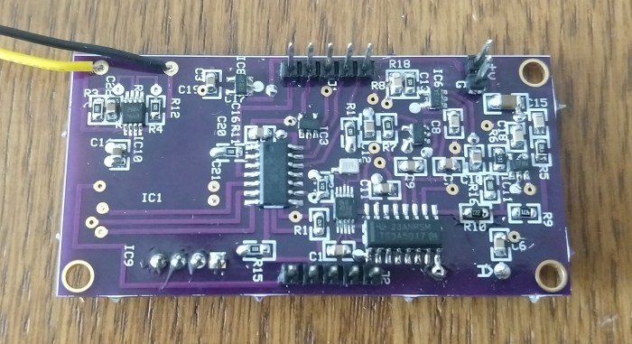
Top view of the circuit board:
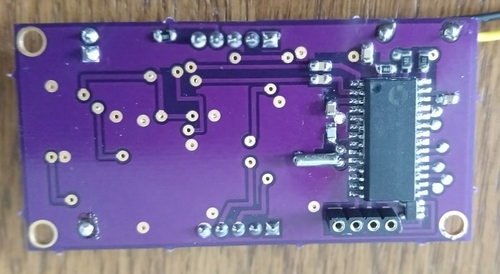
Bottom View Showing FV-1 circuitry
Display board
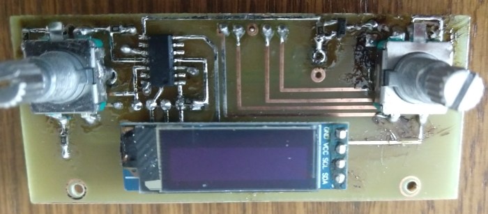
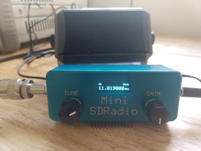
Completed Radio
Demo Videos:

Excellent work — thank you
V
Thanks…I hope someone gets some ideas from my approach. I am surprised that I don’t see anyone using the FV-1 for radio applications. It is by far the easiest way to leverage DSP for such applications.
Brilliant! If this was a kit I’d buy it. 🙂
Couple of questions. I’m looking at the code and noticed in function si5351aSetFrequency() that divider is set for frequencies higher than 5.1MHz, otherwise not set? Also the phase offset is set using a variable called Divider (first letter is a capital)?
In si5351SDR_firmware.c the frequency is restricted to a maximum of 16MHz. Just wondering about that limit. Is there an issue with 90 degree phase shift above that?
Cheers, Ian
Both the PLL and a set of dividers can be adjusted to control frequency. Using both or either is perfectly fine in general, but in order to create quadrature …that stays properly aligned…as you tune…..you can only change the PLL and you need to leave the divider setting static. If you don’t do this, the only way to realign the the outputs as you tune… is to reset the PLL every step. This creates awful chuffing and clicks as you tune. The problem is that one divider setting is not sufficient, with the sweep of the PLL available, to cover tens of MHz. Hence, at certain frequency breakpoints. I change the divider such that desired frequency can be generated without discontinuity. The 16 MHz is just arbitrary…it will work through the 10 meter band. I just wasn’t interested in anything above 20 meters. Thanks for the catch on the D…I was just happy it all worked and didn’t go back to comment much or clean up that stuff.
Hi Ray, here are the lines of code that I’m concerned about:
if(frequency > 5100000)divider = 124;
if(frequency > 9050000)divider = 44;
If frequency is less than 5.1MHz then “divider” will not be initialised (it’ll just have the value it’s currently set to). Looking at the asm it seems that divider isn’t pushed onto a stack and so it might get a valid value by accident since the start up frequency is 10MHz!
yes it only works correctly but its not coded correctly…I need to review how I ended up with that. I think that you just need a test of 9.05 with an if else.. I will test some better code and post it .
Now all I have to do is find someone competent in building it as I haven’t got the foggiest how to do that and besides I lack the fine motor skills required.
really nice design! one question: what is the reason for not covering lower frequencies? I guess some technical issue?
Yes you can only do direct quadrature out of the clk generator chip down to a little under 3Mhz.. This is because the phase shift register can not hold values large enough to get to 90 deg below this. However using the same analog mux as a switching mixer as I do. You can output F and 2xF into the mux select inputs and generate quadrature as well….This can work as low as you want…but beyond about 13Mhz it doesn’t work as well..so I went with direct quadrature. You could create firmware to support both approaches easily in the same design…but there is one issue with this. Two signals out of the mixer have to be swapped when you change from (F: 2xF) and (F : F+ 90deg).
Thanks for the great development. This is the receiver of my dreams, I want to purchase in any form: an assembly kit or an assembled board, or in another form convenient for you. If there is such an opportunity, please contact me by e-mail. I apologize for the presentation style – I use Google translator
I am cleaning up some design features…I need a couple weeks but I can sell you a built and tested board ……you would just need to add connectors and put it in a case. Send me an email to raycharlesring@gmail.com
Ray, this project is so exciting to me, you’ve done something amazing here!
I’d like to experiment with this.
A couple comments:
– VOLMET on 6640kHz is an USB signal, not LSB. You are definitely receiving USB in your video even though your display says LSB.
– is narrowband FM demodulation possible?
Congrats on this project. I haven’t been this excited for a new SDR implementation since the original rtl-sdr drivers came out from Osmocom!
Yes I realized I had My LSB and USB reversed! Thanks for the confirmation…will change my display code so it is synced with the correct mode. I’m glad you like it. I have some cool tweaks I am making to improve the design. I just finished all the changes to go to 48KHz sampling rate for the FV-1…so 24 bit/48KHz for the DSP….plus now I am generating the clock for the FV-1 from the spare output on the Si5351…FM is possible; I just have to write the code for the DSP. I will post my new updates soon …I am going to add another input to the FV-1 to make the filter bandwidth adjustable as well…so a couple minor board tweaks coming too
[…] an audio-reverb chip to do the modulation decoding for an SDR receiver is kind of cool… but might also give some ideas of how to use the FV-1 reverb chip for […]
Where could I learn something about FV-1? Do they exist on a breakout board to play with?
Yes Jim go to spin semiconductor to get the compiler and all kind of technical info. The distributor is Experimental Noize…with a Z https://www.experimentalnoize.com/products_manufacturers.php they have a dev board that operates usb…very easy to use…the compiler is easy to get going as well.
Hello, I looked at both sites. I ordered a module from Electro-Smith (not so complex as E-noize dev kit, but with all functions possible) and it arrived in about 4 days :-).
Please, how do phase the Q signal? What is the principle?
Jindra
there are lots of resources on the internet explaining signal processing quadrature signals…I am not sure what you are asking..is it in regard to DSP coding in the FV-1 or how to generate quadrature signals in hardware which then are inputted into the FV-1?
I mean how are I/Q signals processed in FV-1 (how the program works). In the past I studied a lot about SSB generation and demodulation, especially some 15 years ago when I built Norcal 2030 kit, which uses quadrature detector followed by allpass filters as phasing strip to achieve SSB demodulation of audio signal between 250 and 850 Hz. However, to achieve proper phasing in wide range, let’s say, 300 to 3000 Hz, requires more allpass filters (three or four0 and I would like to understand what the software actually does to implement allpass filters.
In the Tech File, I see the hex file for the PIC, but in the FV-1 folder only source code. Is there supposed to be a hex or binary file to put in the external EEPROM? Also, are the PIC ‘fuses’ set in the hex file, or would I need to manually enter them in the PIC programmer (a PICkit2 Chinese clone)?
The FV-1 hex file is created using the spin semi assembler which is free and very easy to use. The PICs do not have fuses(one time programmable) but a config register…which is included in the hex file. So you need nothing but the hex file. I use the pic kit 2 and the clone version…you do need to get the most recent device file for the pickit for it to recognize this part.
Sorry for the confusion. Many people refer to the config bits as fuses, especially old school PIC programmers and those who used the CCS compiler. They used a preprocessor directive named #fuses to set the config bits in the source code if you wanted to do it that way. But Google “MikroC” “fuses” and you’ll see folk still using the term. Seems like it used to be in the Microchip literature before being standardized to the more descriptive “configuration bits”. — I’ll compile/assemble/translate the FV-1 source code for the external EEPROM and see what pops out. Thanks.
Just started running through the project and noticed input op amp called out as a THS4303 but pinout is for the LT1818. Footprint on PCB Gerber stack is also for the LT1818 in a TSOT-23 package.
typo…. ths4304 is the part…so sorry…darn it!
I’m getting another Mouser order ready. 1.) You actually used the THS4304 in a built unit? 2.) Experimental Noize will sell me onesie-twosies of the FV-1 device that is not on a demo PCB?
Never mind on the FV-1 sourcing. I see it’s a popular pedal component and available elsewhere. Should have looked first, sorry. — The crystal is 40 KHz instead of the typical 32,768 Hz used for the chip. Is this by design or just what you had on hand? A higher clock increases bandwith of the device, as you know. Frank at Noize sticks with Citizen crystals. Is that what you used? I ask because the FV-1 seems a little picky on crystal brands and load capacitances. Your crystal cap is a bit off from datasheet standard, too. I suppose to match the crystal manufacturer’s spec?
Dwelling on the details is so I have the best chance of success on the first try.
Hi,
This is a nice work!
I’m evaluating to build one and started to look at the MikroC code.
It seems it missing a source file that describe some of the functions: EncodIn(), SelectMode(), SelectStep() and others
Could you provide it?.
Thanks!
I will check ..I can provide it of course but I think its there? I will get back in a day or so
Thanks for the quick reply! No hurry.
There are 3 source files in the zip, none of them contain the functions that select the FV-1 bank and send the data to the display, and so on.
Also:
– how do you select the mode (FV1 bank) from the interface? with the rotatary encoder and its swich?
– how to you program the eeprom? with a programmer before soldering it to the PCB?
Thanks,
Claude
I downloaded the files and everyhting is there…not sure what is wrong but if you send me an email. I can assist. raycharlesring@gmail.com
Sorry another question.
Is it possible to output on one of the two analog output, a mixed IQ signal to be able to perform a FFT, to have a vision of the spectrum, if yes what would be the bandwidth? 22KHz or so?
Thanks!
the bandwidth is less than 10 Khz . The FV1 has more limitatations than a sound card. You could I guess but the small bandwidth would make it no so useful
Hey! Very cool project. I am going to try to recreate. Is there a BOM anywhere, or can one be generated somehow? Thanks!
I am going to post a slightly revised schematic, board layout, firmware, etc in the next week or so…I will create a link to tech data
sorry Ray ,wrong information need this project FV1 24LC32 Hex dump code.https://www.adrive.com/public/CpKWsE/Si5351%20SDR%20Data.zip
explode zip file FV1 hex not found,I am beginner not compiled spin program. please updated zip file included 24LC32 hex code .
best reagards..