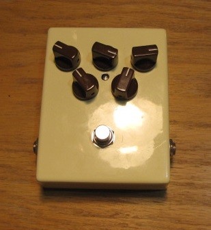
Well, I finally finished my phasing receiver!
I am posting the schematic and design info. I have a surface mount layout which I will post also. There is source code for a micro-controller required. I plan on providing some sample code and I am happy to provide coding assistance. Since there are so many variables with regard to possible features, tuning method, micro-controller used, etc, I probably will not post my source code in its entirety.
I am an amateur radio operator W4KIA and have always loved shortwave radio. I designed this radio to experiment with the basic platform of the Tayloe detector . It is intended mainly for AM shortwave listening – so there is a lack of sharp filters to optimize CW selectivity, etc. The radio is designed to used a random wire antenna for casual listening. I say this because one would want to change the circuit to optimize for amateur radio applications. This design should considered a reference or starting point and not a perfected turnkey project ready to build.
The heart of the circuit is a quadrature sampling detector developed by Dan Tayloe. At first glance, this circuit appears to be to be a switching mixer used as a product detector. This is not quite accurate. It really is a sampling detector which generates a difference beat(when LO is slightly out of tune with the incoming signal), but not a sum product. The very basic idea is to switch on and off a RF input into an audio range low pass RC filter and detect (integrate) the difference beat frequency or modulation envelope, when exactly at zero beat. A simple diode detector is analagous to some degree – the difference is; it self switches so it is always perfectly synchronized to zero beat. Also, a diode only switches on for a portion of a half cycle, hence there are losses.
The fact this is a detector(not a mixer) and that it is quadrature sampling leads to two very important benefits. One, I and Q signals are easily obtained. This allows sideband rejection via an analog all pass filter or DSP processing. Second, it provides near unity gain (since you have no sum product, you do not lose half of your energy in detection, aswell, you detect at 90% of peak not RMS). There is much information on the web describing the Tayloe detector so I will not go into all the detail here but I will describe some of the advantages/disadvantages of the detector.
Advantages:
The sampling detector has large dynamic range – primarily a function of operating voltage of the analog switches.
Unity gain (well almost but much better than a diode mixer/ detector – which will be worse than – 6dB). Quadrature sampling allow for near peak detection instead of RMS and there is not a sum product which otherwise is thrown away and wasted
Requires no tuned circuits and is agnostic to RF below the maximum switching rate the analog switch input can handle ( see disadvantages below).
Its simple and not critical to adjust
Built in front end selectivity – If your input is at 10Mhz and filter knee is at 1KHz(need to double this for the calculation) – you have front end selectivity Q of 10Mhz/2KHz ……which is 5000!
Disadvantages:
It needs to be driven by a Local Oscillator 4X the desired reception frequency. So you need to generate 40MHz and divide into 4 (90 deg phased) clock signals to listen to WWV at 10MHz…OUCH!
It needs to be driven by a square wave – which introduces harmonic detecting and spurious signals. Front end selectivity will mitigate this.
The gain, bandwidth and noise figure of the detector are very sensitive to antenna impedance matching. This requires a well-defined RF input impedance for best performance.
Although much, much, better than beef stew product detectors, it can still experience AM leakage (I have not observed this with my radio but I don’t use a huge resonant antenna either)
Makes a beat note, so AM detection requires careful tuning with a really stable oscillator( This is what I do) or requires tuning above 20KHz, band pass filtering, and summing to full wave rectified output (absolute value circuit) to create AM detection. Alternatively, you can A/D convert and use DSP signal processing.
Basic of the design:
IC1 is a PIC microcontroller used to drive my LCD display and generate the SPI config data for the clock generator IC2. Tuning is generated from a 2bit Gray code mechanical encoder and a push button to select tuning steps(10Hz, 50Hz, 1Khz, 10KHz, and 100KHz). I am using a cheapo LCD for display but it creates noise; so I am going to change over to a charlieplexed 7 segment display or something like that, eventually. Ic2 is a cirrus logic FRAC N synthesiser – CS2000 that I have been able to get to generate output frequencies from 2 Mhz up to 70 Mhz . So dividng this by four, my tuning range is 500Khz to about 17 Mhz. The resolution once divided by four is about 10Hz, using a 22 MHz crystal. One can use a crystal reference as low as 8 MHz but the device generates some spurious birdies from the FRAC N modulation and 22Mhz eliminated the vast majority of these. I think there are two or three spurious signals found across my tuning range, none of which fall in brodcast or Ham bands. The part is very simple to use, has a simple command structure and draws only 10 mA, as opposed to a SI570 which draws nearly 100mA and is more expensive. I looked at making my own PLL or using a DDS chip but neither would give me the desired tuning range and the DDS requires extreme filtering to reduce jitter(even though you are using a square wave). The CS2000 is a great choice for this kind of radio, one just needs to be thoughtful about reference frequency of the crystal.The clk generator drives IC4 which is a 74HC163 counter which counts up to four providing the enable signals to select which analog switch is enabled in IC 5 the FT3252. You can also create a quadrature clk with a couple flip-flops and use other switches such as the 4066. I chose these for two simple reasons, I had them and these IC’s lend themselves to a much easier PCB layout.
IC8 is a 100Mhz bandwidth op amp used to set the input impedance to the detector IC5 at 50 ohms, this along with the resistance across the switches provides the “R” of the RC filter. It also provides some input gain and becomes the dominant driver of noise figure for the receiver. The front end has no pre-selection filtering and there are no tuned circuits anywhere in the design. There is just resistive termination and capacitive coupling. I used a LMH6642 because I had some in a junk box and it draws very little current. It works pretty well up to the 20 meter band and is stable. I can use any old piece of wire as an antenna and still provide stable termination for the detector IC5. This particular op amp does not have the best noise figure but works okay. A better choice would be the LT1818 but it draws more current. It has 400Mhz bandwidth and a low noise figure. One can obviously use a discrete JFET, etc, but I figured I would give this a try and it works fine.
After the detector, there is a very low noise dual op amp to sum the 0/180 deg signals and the 90/270 deg signals to generate I and Q (Inphase, Quadrature) having I and Q is the magic sauce of communication because with I and Q you can determine both phase and magnitude of a sine wave. The signals then go into a three stage all pass filter. This filter has critical 1% tolerance values. For best results you should really grade the components a with a decent multi-meter as close as you can get them. The absolute value of the components is not as important as the relative values. For example, if you chose all the capacitors to be .01uF (as I did) they all can be .011 or all be .095. They just all have to be the same. To design my filter, I used the JTEK filter calculator . I chose one capacitor value and a bandwidth range such that my resistor values could be easily created by paralleling and or series connecting standard 1% values I had. I think my filter bandwidth was 200Hz to 2500Hz or so. I do not specify the majority of the filter components in the schematic, leaving it to the designer chose a bandwidth and component values that are convenient for the builder. Just download the JTEK designer and you can easily create your own parameters
There is low pass filtering from the detector, also some on the summing amps and finally high pass roll off on the final audio amplifier. In total, this does an okay job of restricting the bandwidth for the phasing filter but it is not optimal by any stretch. Normally, one would have some higher order filtering to restrict the range of frequencies going through the phasing filter. If you do not restrict the range for the phase shift filter, the sideband rejection rapidly degrades outside the filter’s design bandwidth. My phasing filter works well enough, providing 30dB (measured) lower sideband rejection. I matched the .01uF capacitors, but did not bother matching the resistors. If you want to change the sideband that is rejected – you have to flip I and Q or take the difference at the output instead of the sum as I have. The audio output goes to IC12, a TPA301 amplifier chip. There is nothing special about this I just had one available, lots choices here.
For AM listening, one could just eliminate the phasing filter and just have some sharper low pass/high pass filtering instead. You could use 2 switches clocked at 1X frequency with one switch getting an inverted clock. You would then use one differential amp to combine the push-pull output.This would simplify the design even further. The main penalty would be for CW reception.
The receiver works great for SSB and CW, where the sideband rejection filter really cleans up the clutter. For AM the, CS 2000 is stable and has enough resolution to zero beat AM station and once tuned is pleasant to listen to.
Note: If you are going to do amateur radio work skip the RF front end and use a well matched (50 ohm) antenna. If you you just want make a nice all band receiver – the RF amp is worth adding. You have to bias those switches to half supply. Currently the RF amp provides this- if you remove it you will need to create a half supply bias with a couple of resistors(10K).
JTEK Link: http://www.werewoolf.org.je/apf.htm
Link to Schematic: This schematic has been updated 11/10/2014 to reflect a minor change on the Cs2000 chip. The clk out pin4 should be tied to pin 5 and the cs2000 configured to use this clk as the reference source

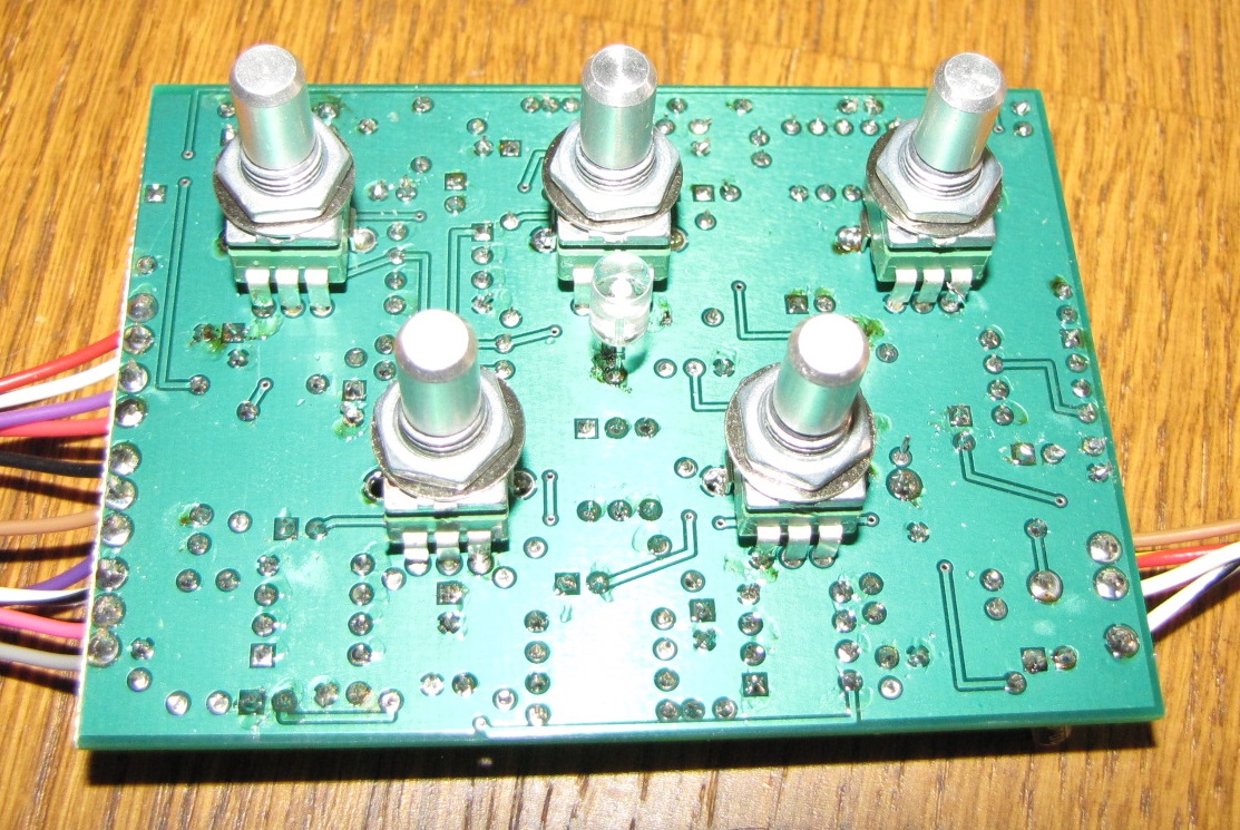
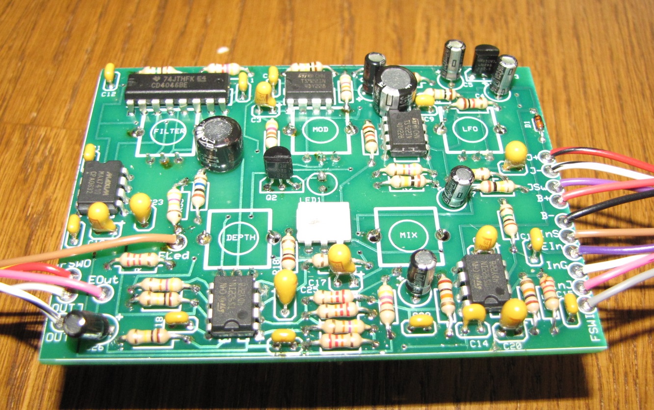
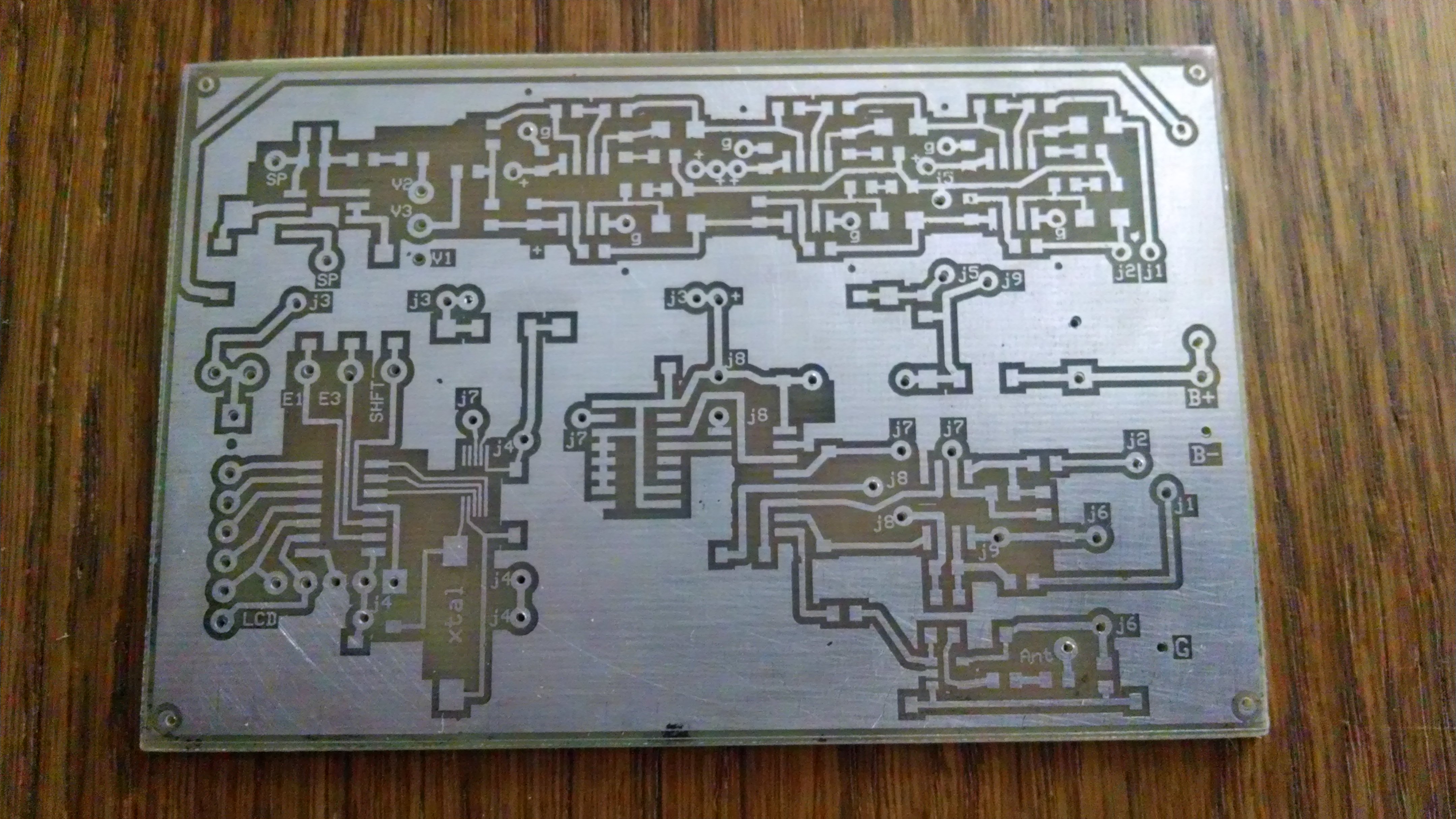
PC Board PIC: This is a homebrew board, created using laser printer toner transfer and sponge/ferric chloride etching.
Layout: (expresspcb file format)
http://www.fileswap.com/dl/c3eTyNWGiI/
Video Demo:
Code Example for CS2000: