
A few years ago, I remember seeing a highly integrated radio transceiver for 433 MHz and 915 MHz. It was produced by Integrated Associates, which then was bought by Silicon Labs. Recently, I found the same part sold by Microchip as the MRF49XA. It is a really cool part, requiring only a crystal and some decoupling caps, if you use the balanced loop antenna as I have in my design. If you use a standard 50 ohm antenna – you will need a few passive components to provide impedance matching and balanced to unbalanced conversion at the output. The radio uses a DC conversion topology and requires no IF filter circuits. It also provide antenna tuning, and internal TX/RX switching etc. Microchip has a very good data sheet which explains how to use the device.
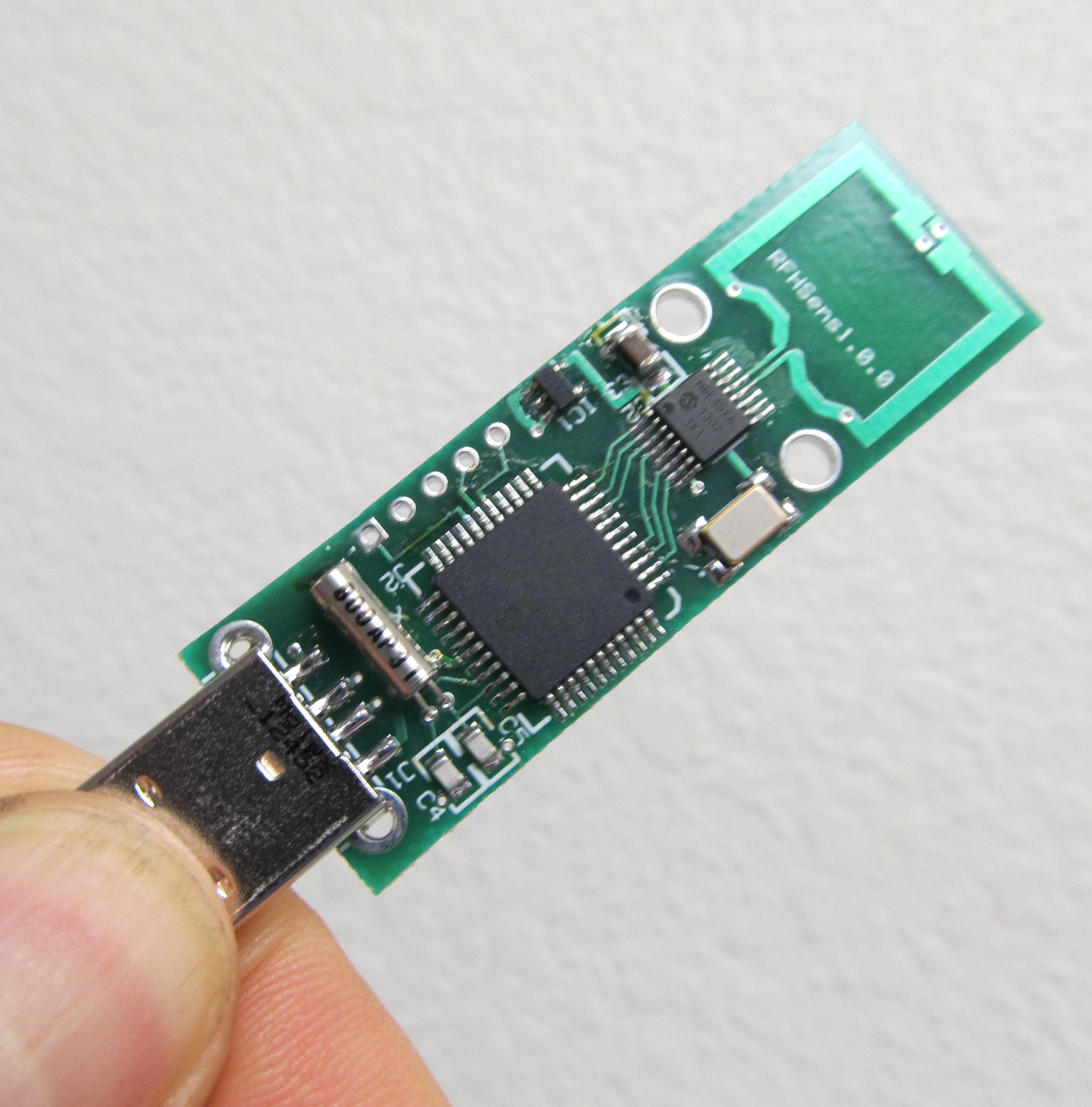
In the picture below is a little USB transceiver I designed to demo the device. I will post a demonstration video showing a couple of these in operation. You can see from the picture, there are not many parts at all (there are two decoupling caps on the back)! The challenge was writing all the code to configure and operate the radio circuit and create the USB link. I created a generic HID USB device which requires no special drivers in windows. I ended up building a complete library of routines to operate the radio and configure its frequency, power, network ID, baud rate, etc…. The device works very well and with this antenna has a range of about 200 -300 feet. Much better performance can be had with a better antenna but this requires more board space and or the matching components discussed above.
more to follow…

I have just finished completing a prototype board trying to use this radio, and attempted to create a pcb antenna using this as a reference: http://www.silabs.com/Support%20Documents/TechnicalDocs/an421.pdf
However, my results were not that great as I am only seeing about a foot of transmission before my communication drops off. One guess I have for the cause of bad transmission is that I did not isolate the antenna from the power/gnd planes, but am not sure. Would you mind posting your eagle files or the reference you used for the pcb antenna? The only other explanation would be register initialization, but I am pretty sure those are correct.. would be great if you could post your register initialization values as well.
Any help would be much appreciated 🙂
I will email you some info in the next day or so, hopefully it will help. I get about 80 yards line of site.
Hi! excelent project! i love it! Im developing something like this, im using the exact same antenna, but also have only a few inches of range, could you give me some hints about initialization, parameters, etc? I already made it work for 433 mhz (using other antenna).
I have done extensive work with this chip and can help you. I will send you an email with more detail. The design of the loop antenna is very critical so the first thing to determine is if the antenna structure is correct.
Hello! I too have included this cross-loop antenna in my circuit for simple short range communications after reading your post. I’m wondering how important the PCB thickness will be. Is it crazy to do this antenna on a 0.062″ board? I know the specification calls for 0.5mm or 0.02″ thickness. I only need about 15 feet of range to a MiWi – WiFi gateway. Can you send me your helpful email too?
yes I will send you an email. I will forward what I sent to CHAMP. Yes the board thickness is critical and antenna performance suffers horribly with the slightest deviation from required dimensions. Having said that, once you get it right it is easy to reproduce. I have a well performing layout for 1/16th inch I will send you
Hi,
could you give me more details on your interesting project, especially the antenna?
I also want to use the MRF49XA from Microchip.
Could you share your schematics and board layout?
Thanks and best regards,
Gernot
I will try and post some more detail this weekend. The loop antenna works well for its size and eliminates the need for a matching network. I will generate some simple demo code that might help get you started also
Hi,
for the code there shouldn’t be problems as I already have the necessary informations, but for the layout/board with PCB antenna I couldn’t find any good informations yet. Most applications use an external one.
I am looking for a very small board with PCB antenna, exactly as yours is.
What is the approx. indoor range and would you share your eagle files via email?
Thanks!
Gernot
Does the board has to be dual layer or is it possible to make also a single layer board?
Hi Gernot,
I found the following documents extremely helpful when designing the PCB antenna, as well as some input from Ray 🙂
Different PCB Antenna Layout Specs:
http://www.sekorm.com/Ectm/23121
General Info on PCB Antennas:
Click to access an422.pdf
I get over 150 ft non line of sight from the downstairs of my house to the upstairs using the 915 MHz Xtapped “Big” loop. The top link also includes the design details for the antenna Ray is using as well (Xtapped “Small” loop). If you go with the “Big” loop design, note there are some discrepancies in their spec, I just went with the average of the possible differences.
Hope this helps,
Kyle
Could you please tell me if there are any formula for the relationship between PCB thickness and the loop antenna?
I am doing something with the 433MHz. I found some information about PCB cross-tapped loop antenna, but it is for PCB with 0.5mm thick only.
Thank you very much!
Rex
Sorry for necro-posting. I am working on a project using mrf49xa and looking at the picture you just connect the PCB antenna to RFN and RFP pins directly without any balancing circuit. The datasheet says that mrf49xa requires impedance matching balun circuit between pins and the antenna and provides the schematic. Did connecting the antenna directly to pins just work for you? Did it damage the chip? What was the transmission range? Did you do anything special to make it work?
Actually, it is a balanced tuned resonant loop antenna with no ground reference. The + supply is connected to the center of the loop – and the two ends are connected to the the differential outputs. The loop uses two layers with tuning capacitors formed between the top and the bottom of the loop. Its a physically small antenna but I can get 200 feet or more with it…at full power.
The range great for so few components. Antenna design so elegant without matching components. Is there any guide so we can adapt for a 868Mhz design?
So this part is now obsolete…there are some very similar parts from silicon labs that will work and that could be adapted for that frequency range
Thanks. You think the antenna design work with the Silabs option?