
I have built countless regenerative radio circuits throughout the years and some have worked well – some haven’t. I was inspired by the circuit design of the TEN TEC regenerative radio kit. I used some of the same ideas, but changed the design to better match my design criteria. In this design, I had eight important design objectives:
Simplicity – this type of radio should not be complicated and I have seen designs on the web that may perform well, but seem unnecessarily complicated.
Tuning/fine tuning – I use a cheap poly variable for main tuning and a junk box rectifier as varactor for fine tuning.
No special inductor required – I have tried all sorts of junk box inductors and they all work great. With this design, no tapped coils or tickler windings are required. This design could easily be made into a multi-band radio
Extremely smooth and stable Regeneration control – I adjust a DC bias point condition instead of RF Feedback to control regeneration and the performance is excellent. There is no hysteresis or abrupt transition from regeneration to oscillation.
Ample Audio Gain with no motorboating or instability – I stayed away from the LM386(which could be used) and chose a TPA301 amplifier IC – which give excellent results.
Antenna Isolation – This is achieved with a simple grounded gate input stage which shares the LC tank with the oscillator.
Excellent sensitivity – This design is the best performing Regen I have ever built
No critical adjustments and easily repeatable results – I have built this circuit now three times with different inductors, for different bands and with different JFET device types on bread-boards, etc. The results have all been the same and I have only had to make minor tweaks to optimize performance for different JFET types and significantly higher or lower frequency bands. The radio currently tunes 7-11MHz.
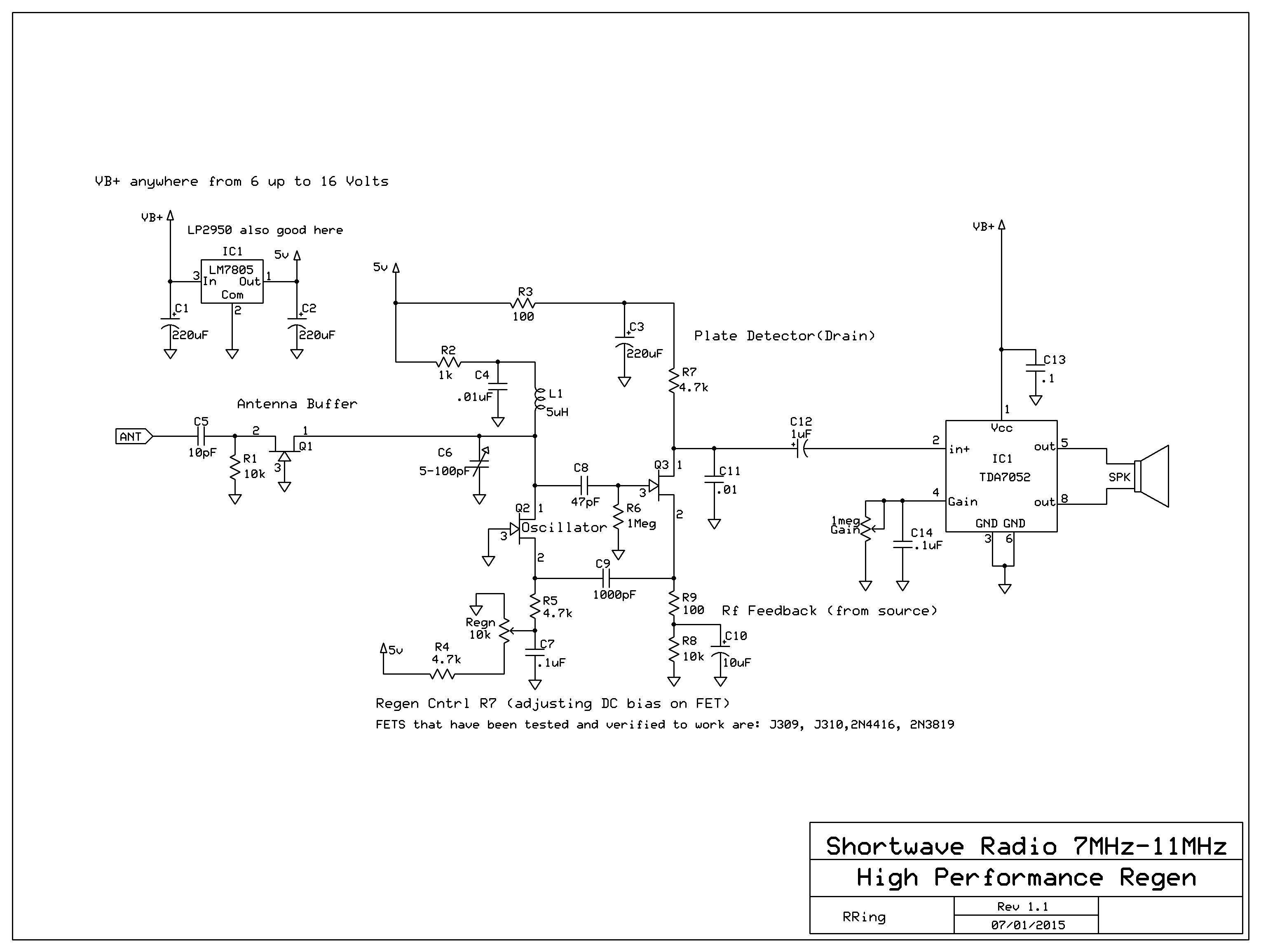
The basic paradigm of this design is to break up the traditional oscillating detector into a separated regenerative amplifier and detector circuit.
The detector is a “plate detector”, where RF is fed back to the Amplifier via a partially RF decoupled source(normally bypassed all the way for RF when used as a detector).
schematics:
Version 2: (07/30/2015)
Link to PCB for version 2:(expresspcb format)
https://www.adrive.com/public/NPY7VM/Simple%20Regen.pcb
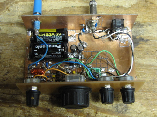
Version 1 (shown in video):
picture of prototype:
Video Demo:

Hi Ray !
Always wanted to build a regen. I think your design will be my first. I have most of the parts and will start pulling them together tomorrow. Very nice thread and you follow up well. I will let you know when I get started.
Thanks and Merry Christmas to you and All the regen buffs !
Jim WB4ILP
Great! lots of people have built it successfully. If you have any issue by all means reach out…..
Hi Ray !
Thanks for the reply. I was wondering how the plastic cased polyvaricons compare to standard air variables. I have read that they are far inferior to a good air variable but I’ve also read that they work well. ??? They obviously work well in small transistor radios and they’re available for cheap on eBay. I ordered some last night.. I have a couple of table top AM/FM radios picked up at yardsales that contain a nice air variable. Also, how well would a PTO work in your design? A variable core inductor with fixed capacitance, maybe switched fixed caps. This might help some builders work around the need for a variable cap.
Jim
I am unable to open the .pcb file . Could you please help post or email me a copy of the pcb for Laser printing?
Many thanks!
Could you also tell me the inductor values for the other SW bands ?
thanks
The Poly caps work well for me…They are inferior for applications requiring high voltage tolerance, high power such as in transmitting loops. They also have more drift but they work fine for receivers. They best place to make improvements is in the construction of nice RF coils. Yes a well constructed air variable is better but it seems a waste to invest in a really nice one for a regen!
Hello Ray!
Thanks for a great circuit. Can it uses on long wave to? 140khz to 300khz ?
Best regards
Lars vinghest
it should…give it a try
Yes, ones I built did work on LW, MW, and SW up to about 12MHz with J309 FETs. I have built this circuit and experimented heavily with values to get it to work with different coils and frequency ranges.
Using the version 2 schematic as a reference. Increasing R9, decreasing R8, increasing C8 and C9, and decreasing R5 were needed to get consistent regeneration across MW into LW when I was using a large ferrite rod antenna.
Bottom line, I found it helped greatly using trim potentiometers during the experimentation. Try it and see how it goes.
One note is that as C6 increases to very large values, above about 500pF, it seemed like sensitivity dropped a little bit.
One final note, I used a basic NPN amplifier buffer instead of the TDA7052 as I use an external amp speaker.
Ahh that’s great a fellow experimenter doing cool stuff
Thanks Ray! And thanks dakhobby!
What a great construction!!
Real nice!
Have a good day to your both
Many regards
Lars
Good evening, Mr. Ring. Happy new year to you and your family.
I have recently built a high performance regenerative receiver that uses the same concept as your original one except it uses a high impedance detector, an AGC circuit, and an RF preselector front end. Once I got the radio working, I am pleased with its performance, given its minimal parts count.
Built on a homemade printed circuit board, it’s construction is stable.
My version of the Circuit Salad regenerative receiver currently covers the entire AM broadcast band but can be modified with a bandswitching RF coil circuit that can provide continuous coverage from approximately 520 kHz to 30 MHz in four tuning ranges.
Since the late 2000s, when many government-owned and run shortwave stations shut down their transmitters, I can only receive transmissions in Spanish from Cuba and religious broadcasts from the United States, and on occasion, news in English from China and Japan.
Thank you so much for sharing your article with us, and I look forward to hearing from you soon.
I just built this and it works. Fet from antenna was BF245, then the others were 2n5458.
1st made it didn’t works if use a 1sv149 varactor and wirewound multiturn pot. I don’t know why ?
Then it works with Polyvaricon 300pF.
Reduce the coil from 4.5uH to 3uH or less does not effect the frequency range so much, it covers 4.1 to 13.6 Mhz.
1 transistor preamp emitter grounded followed by 100k Ohm series before ready made tda2003 amp kit.
Sound plenty and excessive.
The performance compare to Kitchin N1TEV high performance regen is almost same.
Hello Ray
After used for a month, could you please suggest, how to make regen potensio smoother or how to add a fine regen pot ?
Thanks
something is odd here mine is very smooth and gradual in transition. There must be something not quite right with your circuit. Start by lowering the supply voltage some and see how it behaves