

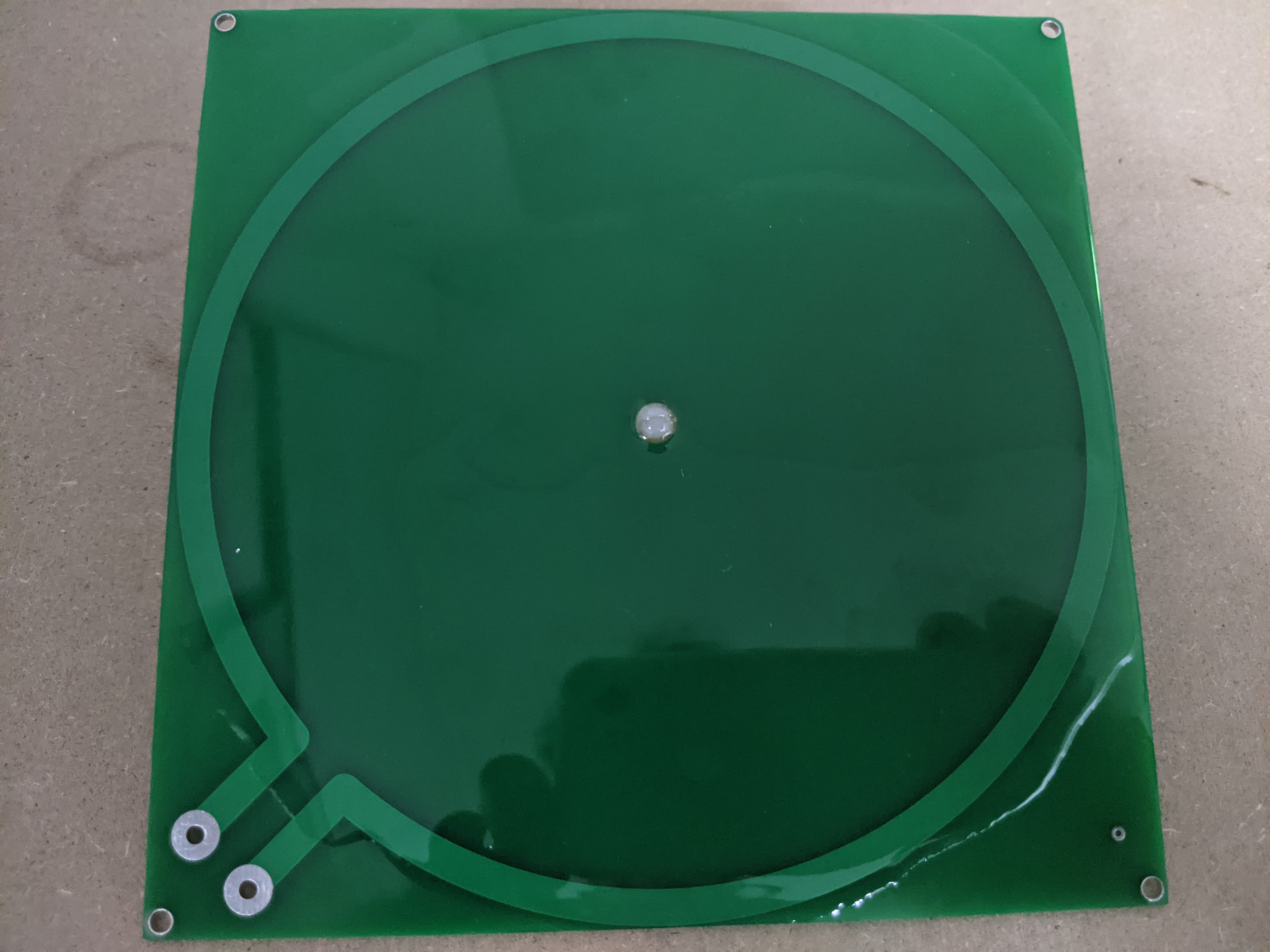
I have seen a number of low output PCB etched spiral Tesla coils on YouTube and wondered if the they could be driven to produce the larger outputs of traditional cylindrical coils. After designing my McTesla Tesla coil, I decided to try driving a PCB etched coil with my non resonant half bridge driver circuit. I first etched my own home brew coil which was 150 turns with an 8 mil trace spaced 8 mils. This worked with modest output but the frequency was higher than I desired at more than 2 MHz. So I broke down and had a commercially etched board made which was 6 inches square and has about 240 turns with a 6mil trace spaced 6 mils.
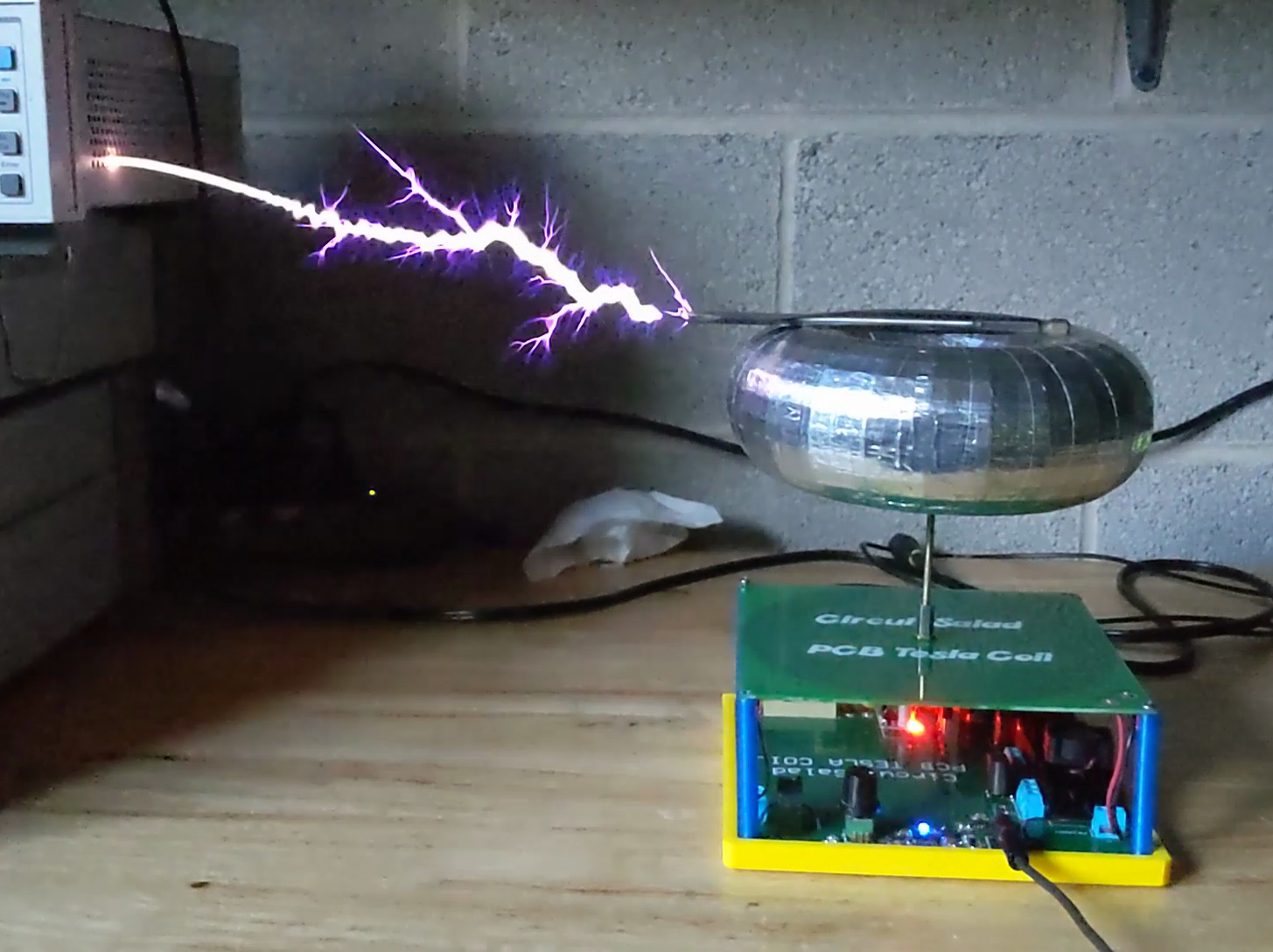
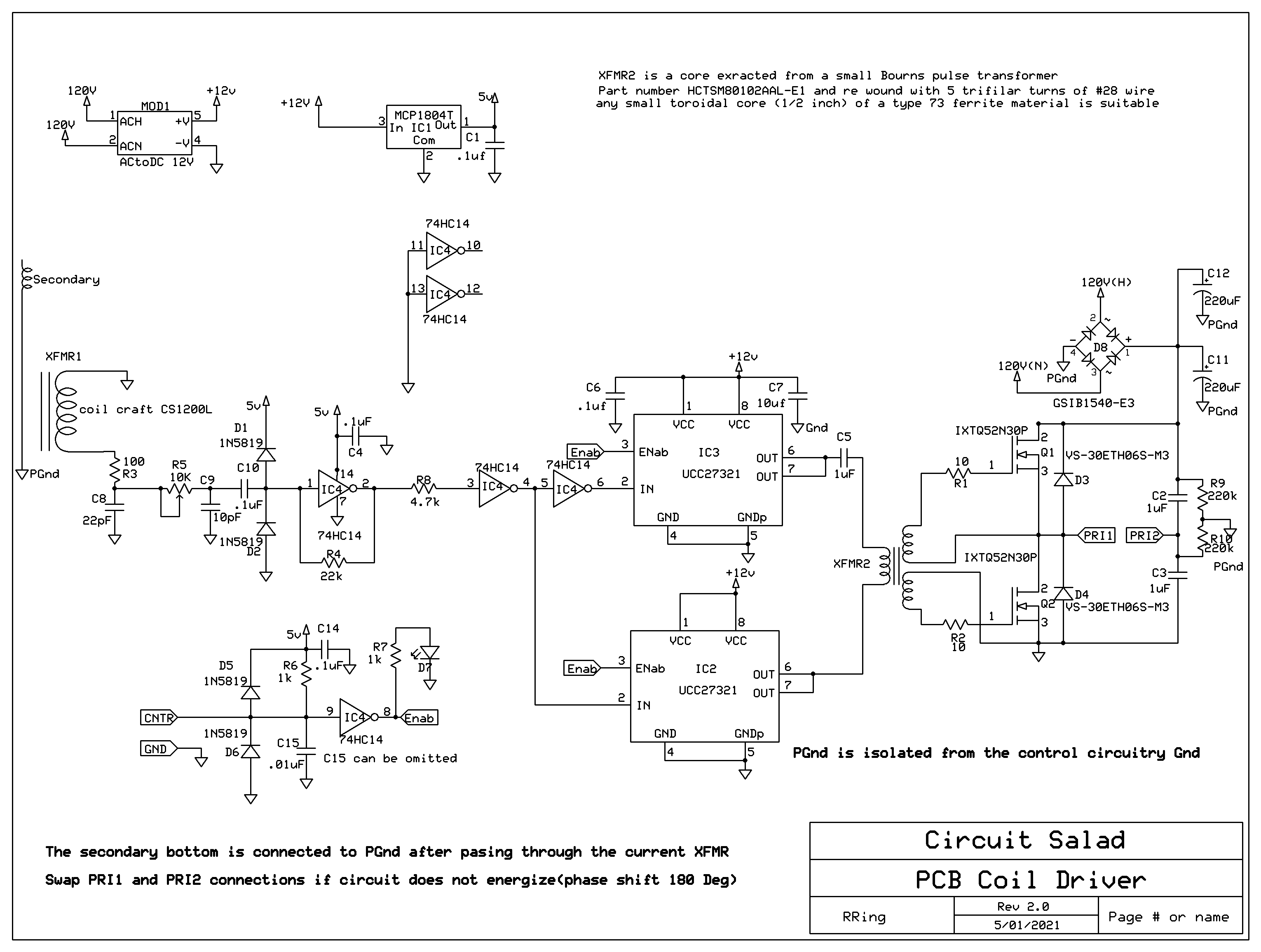
This coil performs well and depending on your top load resonates at anywhere from 900 kHz to 1.2 Mhz. The driver circuit is essentially the same as in my other designs. There are minor tweaks of the phase shifting network in the feedback path because of the higher frequency but everything else is the same. My top load is a 3D printed toroid which was wrapped in aluminum tape. The primary is one turn of etched on the bottom layer. Though the coil works quite well, it has to be carefully structured to avoid inter coil arching and breakdown.
My other coil designs utilizing this half bridge driver can achieve 9-10″ streamers. Surprisingly, the PCB etched coil can produce 12 inch streamers. To achieve such high output without the coil breaking down; I had to encapsulate the secondary in two part epoxy compound. Also the center post, connected to terminal, is screwed down to the secondary center with a nylon screw. A brass washer soldered to the center is the secondary output connection. There can be no metal screw passing through the PCB or it will fail to the primary or arc across the secondary on the top. Two part electrical potting compound works well to protect the coil and is easy to apply. It will harden in about an hour in a warm oven (170F). Both the top and bottom are potted. This coil uses the same interrupter circuit as the McTesla. The break out point is critical and the mosfets will immediately explode if the breakout point is not present. The breakout point can point up or to the side, but you have to be careful to make it extend an inch or more out from the terminal to provide adequate break out.

[…] proposition, both in terms of the function and the aesthetics of the final product. So this high-output printed circuit Tesla should take away some of that tedium and […]
This is a very nice project. I am very impressed by the output of the coil. All the other PC based teslas I have seen have tiny Slayer type outputs ie a little brush discharge.
I’d imagine finding a PC maker that will deal wit the fine lines over a large area (the secondary) might be difficult. Who did you use?
Cheers.
https://jlcpcb.com/ they made me 5 boards for $23.00 they also made the driver board which I had done in 2oz copper.
That is a really cool project, seeing that you are able to push such long sparks through a PCB secondary coil… quite impressive indeed!
Your project was posted on HVF: https://highvoltageforum.net/index.php?topic=1617.msg12422;topicseen#new
Thanks..yes when I started i wasn’t sure what kind of performance I could get. Having the top load really help the coil from breakdown arcing. Initially I had problems with the spirals breaking down. Getting really long arcs is about efficient coupling of as much power as possible and being able to store it not radiate it(corona leakage..etc). The single turn primary is impedance matched and closely coupled so there is good power transfer. The only drawback of this coil is that it heats up quite a bit. When I run it uninterrupted…it will get dangerously hot in 30 seconds or so. I typically run it at 10-25% duty cycle, which works well. The DC resistance is around 200 ohms and the Q is about 60-70
This is a really interesting project I would like to build.
Is there a parts list available?
The download link has the schematic which has all the parts identified…in the expresspcb tool you can create a bom from the schematic. The caps are 1206 mostly and some 805 packages…the resistors are 805. based on the layout you can easily determine the IC packages etc. I can answer specific questions if there something is unclear
Thanks for the pointers, Ill give it a go!
You definitely need a terminal for longest spark length and to suppress arching. also you need an interrupter, which initially can just be a momentary switch contact for testing.
Thank you for publishing your driver circuit! I very much like to build and use it in my first serious tesla coil project. Problem is though, that I live in Germany and we use 230V. Would it be as simple as switching the MOSFETs for 400V types, assuming RdsOn, gate capacitance and max. current are comparable? Am I right that changing the values of C2/C3 modifies the amount of energy per pulse and would have to be lowered or at least adjusted to the higher voltage and different inductance of my primary coil? Thanks in advance!
I think there would have to significant changes to run it at this high a voltage…I am really pushing the coil hard at 120VAC. The PCB coil would likely breakdown and not survive!
This looks amazing. Do you know how much input power this is pulling?
A few years back I repackaged one of the ebay/alibaba ’10cm’ PCB coils into a top hat, powered via a 60V DC-DC converter, driven by an 18V Makita drill battery in a belt pouch. I am thinking your design would make a nice upgrade. Presumably it’s fine to skip the rectifier stage and feed it ~160DC directly?
yes the peak current is enormous and the 60hz ripple actually creates ramping…extending the spark length as it goes in and out of phase with the interruption. i would suggest something less than 160 at least at first