
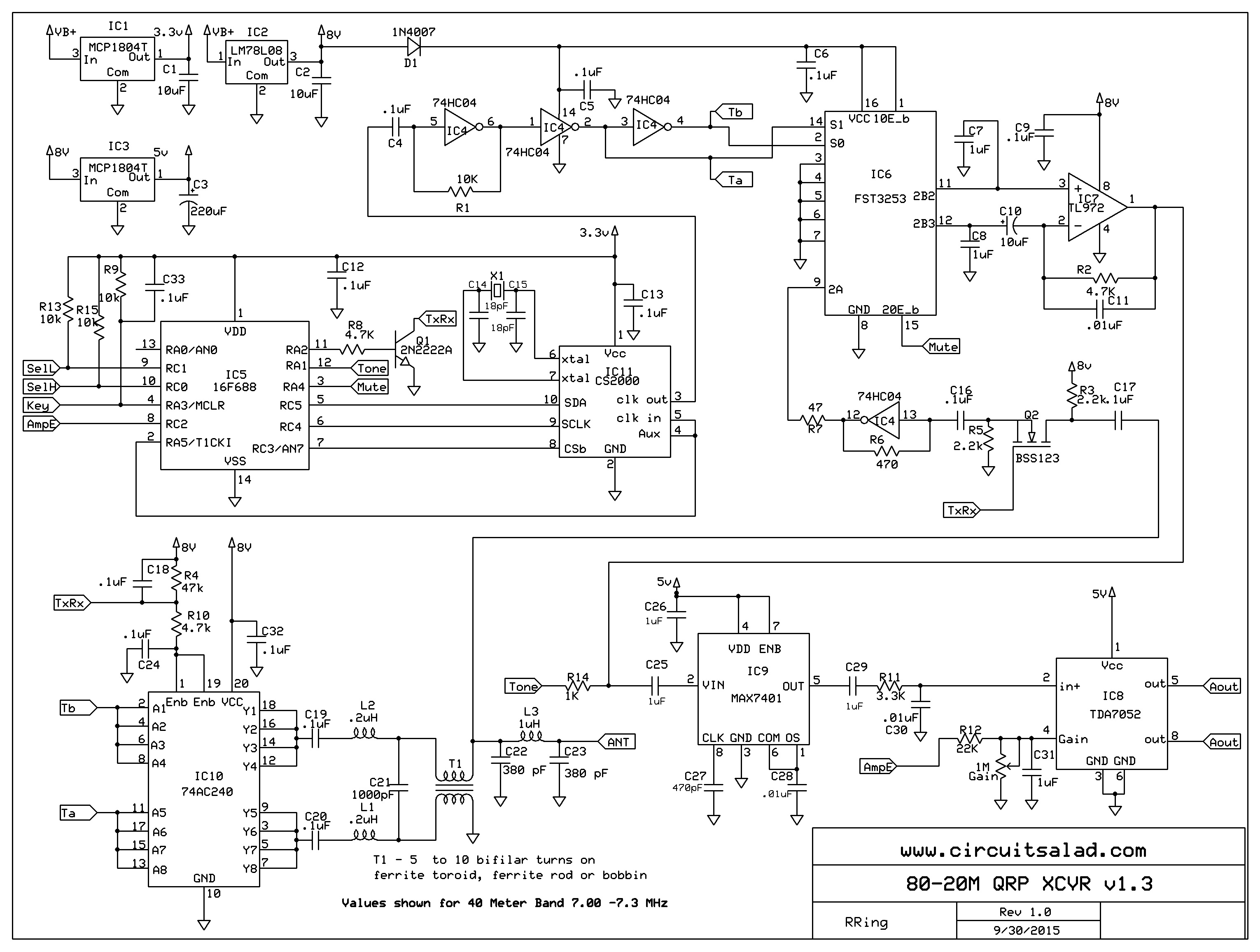
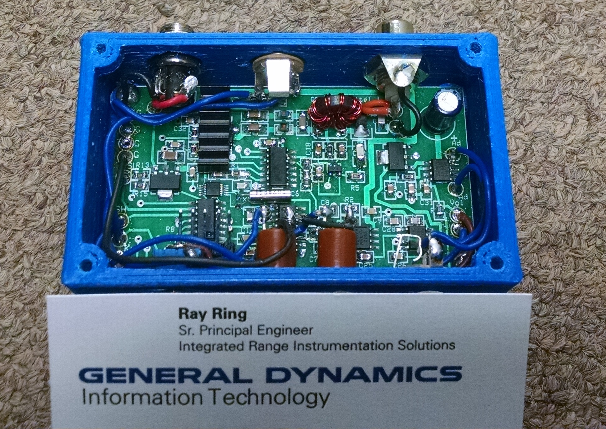
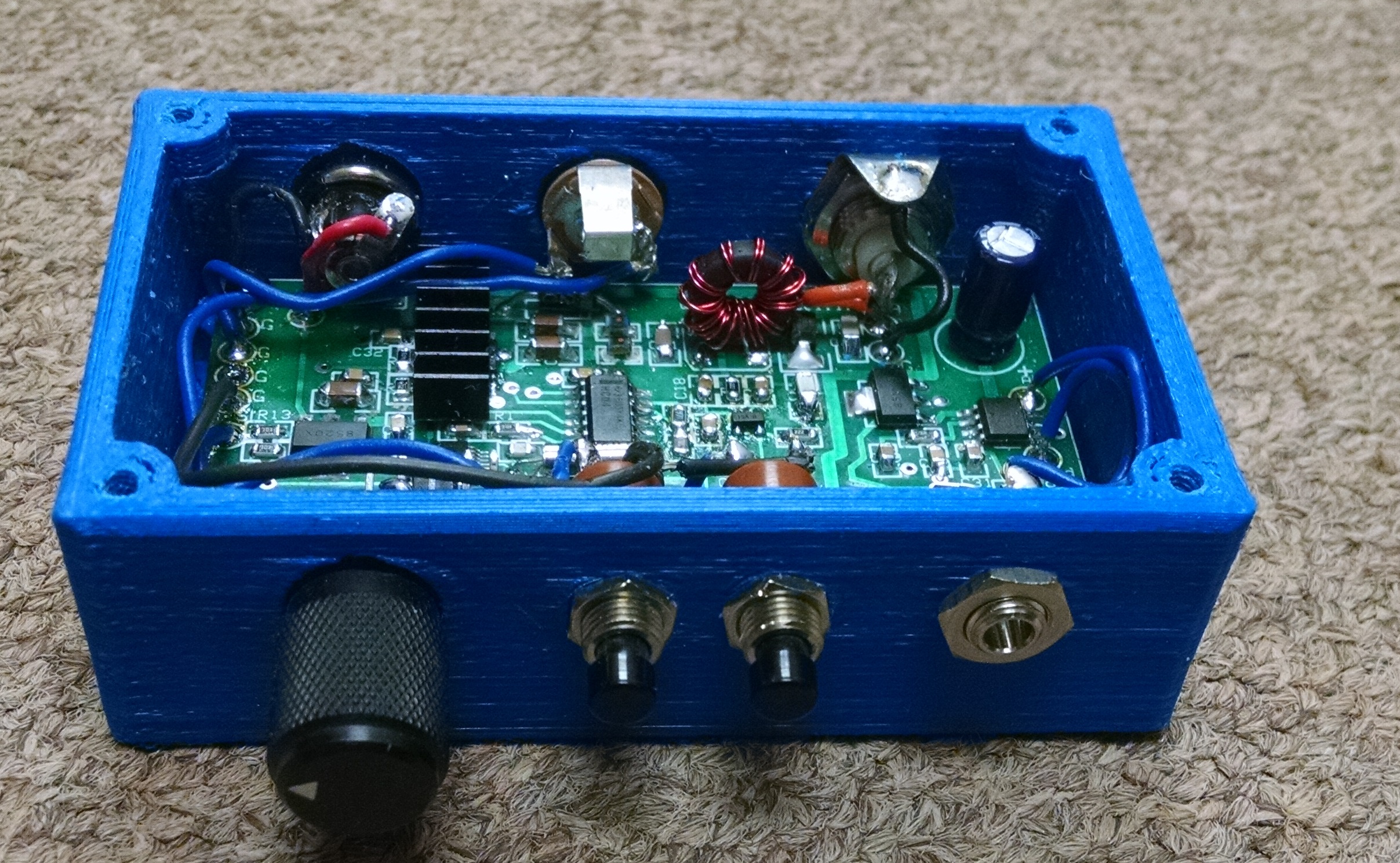
I tweaked my previous XCVR design to use push button tuning and made the board layout extremely compact. I improved the side tone injection to be absolutely perfect – not too loud, full break in and no clicks. I went ahead and integrated my switch cap 8 pole CW filter. The schematic is fairly simple with 65 parts or so.. and the whole design fits into a 3D printed enclosure the size of an business card. The only penalty in the design is signal on both side of zero beat(direct conversion). There is no AM leakage though and the filter rolloff is very good. The circuit is easy to build as it required no adjustment, or alignment, but uses some fine pitch surface mount parts requiring a very precise soldering station. When I got my boards in I literally just built it – applied power and starting using it. In this one I used a ferrite toroid for the Sorta-Balun, but I have used scrap bobbins from HF power inductor for this with great success . The push button tuning works well, it has freq (up/down) buttons which shift through at 10 Hz increments for 5 sec then goes to 1 Khz. It can run on a 10 to 24 volts supply. The 8 pole audio filter is adjustable to taste, by changing one capacitor(C27), and the side tone injection level with one resistor(R12). The choice of band only requires a firmware change and 3 inductors and three capacitors – which make up the RF matching filter. Its really a unique little transceiver. Its very small, reliable and has excellent performance. The TX frequency is offset 700Hz above receive frequency, but this could be made adjustable if desired(using the push buttons and the Key) – I just haven’t done it yet.
Schematic
The built XCVR
I am going to provide a link to all the design files in the next few days including the 3D print files for the enclosure. I am also going to sell a couple units at cost(get rid my extra boards!) as partial kits( I will put most of the surface mount components on) and provide the switches and connectors that fit the enclosure (which I will also include). Will probably be around $70 for everything for a complete unit(except wire).
Link to design files:

Hi Ray — looks great. Many thanks. Love your innovation. Above all, I’m interested in your clock CS2000 series Will you provide your source code for study? Thanks V.
Yes I have posted some demo code from earlier experiments but in the next day or so I can just post my code for this XCVR which is not that complicated and should be helpful..I will try to comment it so as to be intelligible
The CS2000 is easy to work with and doesn’t use much current. I think the SI5351 is cheaper(1.00 instead of $4.00) but uses more current and I am so vested in using the CS2000..I haven’t bothered is messing with the SI5351 yet. The CS2000 is a SPI programmed part and requires three config lines: nSel, Data and Clk. All you have to do is make a little spi write routine and load a few config registers and then load a frequency value when you want to tune. You need to deal with float and unsigned long variables so I write in C.
Here is my code for the XCVR
Much of it you can ignore but it should be pretty easy to pick out the relevant parts
//Clock Generator Development Code based on the CS2000 FRAC N PLL and 16F688 PIC
//compiled using mikroC from Mikroelectronica.
//definitions below relate to PIC 16F688 specifically and would be changed for
//different microcontrollers
#define nSEL portc.b3 //out
#define SCLK portc.b4 //out
#define SDO portc.b5 //out
#define SelH portc.b0 //in
#define SelL portc.b1 //in
#define Tone porta.b1 //out
#define Tx_en porta.b2 //out
#define Key_b porta.b3 //in
#define Mute porta.b4 //out
#define AmpMute portc.b2
#define HiZTone trisa.b1 // make tone output HiZ
#define HizAmpMute trisc.b2 // make AmpMute output HiZ
#define Offset 500 //TX frequency offset
///////////////////////////////////////////
///////////////////////////////////////////
//these constants all depend on crystal freq used////
const unsigned int BandShift1K = 819; // for 1k
const unsigned int BandShiftFine = 10;
const unsigned long FreqMin = 5733475;//7.000 MHz
const unsigned long FreqMax = 5856335;//7.150 MHz
const float CalcConst = 1.22090; //based on 10.240 xtal but adjusted slightly for xtal tolerance
//CalcConst = CrystalVal/(1048576 * 8) ……(1048576 is 2^20)
//frequency value to use is: desired freq/CalcConst
////////////////////////////////////////////
float FreqValue = 5815382;//initial freq setting 7.100 MHz
char Byte4;
char Byte3;
char Byte2;
char Byte1;
unsigned long FreqPrintVal;
unsigned long TuneTemp = 0;
char FreqString[12];
char KeyFlag = 0x00;
///////////////////////////////////////////////////
void Dot(){
char cnt;
for(cnt = 0; cnt < 50; cnt ++){
Tone = 1;
delay_us(500);
Tone = 0;
delay_us(490);
}
delay_ms(65);
}
///////////////////////////////////////////////////
void Dsh(){
char cnt;
for(cnt = 0; cnt < 150; cnt ++){
Tone = 1;
delay_us(500);
Tone = 0;
delay_us(490);
}
delay_ms(65);
}
///////////////////////////////////////////////////
void Spc(){
delay_ms(130);
}
///////////////////////////////////////////////////
void Morse(char CharIn){
switch(CharIn){
case 0: Dsh();Dsh();Dsh();Dsh();Dsh(); break;
case 1: Dot();Dsh();Dsh();Dsh();Dsh(); break;
case 2: Dot();Dot();Dsh();Dsh();Dsh(); break;
case 3: Dot();Dot();Dot();Dsh();Dsh(); break;
case 4: Dot();Dot();Dot();Dot();Dsh(); break;
case 5: Dot();Dot();Dot();Dot();Dot(); break;
case 6: Dsh();Dot();Dot();Dot();Dot(); break;
case 7: Dsh();Dsh();Dot();Dot();Dot(); break;
case 8: Dsh();Dsh();Dsh();Dot();Dot(); break;
case 9: Dsh();Dsh();Dsh();Dsh();Dot(); break;
}
Spc();
}
///////////////////////////////////////////////////
void SoundFreq(){ //converts generated Freq to Morse Code
if((SelH)&&(SelL)){ //if both buttons pressed
Mute = 1;
AmpMute = 0;
HiZTone = 0;
HizAmpMute = 0;
FreqPrintVal = (CalcConst * FreqValue) ; // divide by 4 using
longToStr(FreqPrintVal, FreqString); //with quadrature divider
Morse(FreqString[5]-0x30);
Spc();
Morse(FreqString[6]-0x30);
Spc();
Morse(FreqString[7]-0x30);
HiZTone = 1;//make open circuited
Mute = 0;
delay_ms(10);
HizAmpMute = 1;//make open circuited
}
}
///////////////////////////////////////////////
void SPIWrite(char SpiByte){
char i; SDO = 0; SCLK = 0; //write a byte of data serially
for (i=0;i<8;i++) { //data loaded when clk is low, must be read
if(SpiByte & 0x80) SDO = 1;// when clk is high
else SDO = 0;
SCLK = 1;
Nop();
SCLK = 0;
SpiByte = SpiByte << 1;
}
SDO = 0;
}
////////////////////////////////////////////////////
void SPICommand(char MAddress, char SpiByte) {
nSEL = 0;
SPIWrite(0x9E); //all CS2000 ships use this first byte
SPIWrite(MAddress);//register address to be written
SPIWrite (SpiByte);//actual data
nSEL = 1;
}
///////////////////////////////////////////////////
////////////////////////////////////////////////////
void SetFreq(unsigned long FreqCalcVal){
SpiCommand(0x06,((char *)&FreqCalcVal)[3]); //Freq higest byte pointer
SpiCommand(0x07,((char *)&FreqCalcVal)[2]); //Freq higher byte pointer
SpiCommand(0x08,((char *)&FreqCalcVal)[1]); //Freq high byte pointer
SpiCommand(0x09,((char *)&FreqCalcVal)[0]); //Freq Low Byte pointer
}
///////////////////////////////////////////////////
void TuneHigh(){//encoder push button read routine
char TuneCnt = 0x00;
while((SelH)&&(!SelL)){ //porta.b3
delay_ms(35);//slow down change rate
if(FreqValue < FreqMax){
if(TuneCnt FreqMin){
if(TuneCnt < 250){
TuneCnt ++;
FreqValue = FreqValue – BandShiftFine;
SetFreq(FreqValue);
}
else{
delay_ms(180);
FreqValue = FreqValue – BandShift1K;
SetFreq(FreqValue);
}
}
else{
FreqValue = FreqMin;
SetFreq(FreqValue);
AmpMute = 0;
Mute = 1;
HiZTone = 0;
HizAmpMute = 0;
Dot();
Mute = 0;
HiZTone = 1; //make open circuited
delay_ms(10);
HizAmpMute = 1; //make open circuited
}
}
}
/////////////////////////////////////////////////////////////////////////////
/////////////////////////////////////////////////////////////////////////////
void Init_Main(){
OSCCON = 0x00; //using CS2000 ref clk as pic clk
INTCON = 0x00;
ANSEL = 0x00; //make port c digital I/0
CMCON0 = 0x07;// make port c digital I/O
trisa = 0b00101000;
trisc = 0b00000111;
nSEL = 1;
SCLK = 0;
SDO = 0;
////////////////////////initialize CS2000 here///////////////////////////////
SpiCommand(0x05,0x09); //freeze output until all writes completed
SpiCommand(0x02,0x00); //first config reg (all 0's)
SpiCommand(0x03,0xC1); //ratio 8 selected, data enb1 set , R-mod 1to1
SpiCommand(0x16,0x10); //config to use OSC 16…0x08
SpiCommand(0x17,0x10); // PLL output when unlocked
SpiCommand(0x04,0x00); // Lock sel=00 (matches ratio select) so FracNsrc must be 0 also
SpiCommand(0x1E,0x00); //freeze output until all writes completed
SpiCommand(0x05,0x01); //freeze output until all writes completed
trisa = 0b00101011;
Tx_en = 0;
Mute = 0;
Tone = 0;
AmpMute = 0;
HiZTone = 1;
}
////////////////////////////////////////////////////////////////
void main() {
Init_Main(); //initialize settings and defaults
delay_ms(100);
SetFreq(FreqValue);
while(1){ // forever do this
if(Key_b == 0){
if(Key_b == 0){
AmpMute = 0;
HizAmpMute = 0;
FreqValue = FreqValue + Offset;//Tx offset
SetFreq(FreqValue); //if change in encoder set new freq
KeyFlag = 0xFF;
HiZTone = 0;
delay_us(3000);
Mute = 1;
Tx_en = 1;
while(Key_b == 0){
Tone = 1;
delay_us(600);
Tone = 0;
delay_us(600);
}
HiZTone = 1;
}
}
if(KeyFlag){
Tx_en = 0;
FreqValue = FreqValue – Offset;//TX offset removed
SetFreq(FreqValue); //if change in encoder set new freq
KeyFlag = 0x00;
delay_ms(10); //was 20
Mute = 0;
delay_ms(5);
HizAmpMute = 1;
}
SoundFreq();//generates Morse code frequency indication
TuneHigh();//sets tuning based on button press
TuneLow();
}
}
Hi Ray,
I like what you are doing in your blog. Is the transceiver rf-amp really an 74HC04 or are you using the unbuffered version? – Thank’s
Yes it works surprisingly well as an small signal RF amp at least for 40 meters!
Could you post an explanation on the general work of your design? Thanks!
Yes will take a little bit….In remote location for next two weeks
Do you already have available the link to all the design files including the 3D print files for the enclosure?
Also, do you still have available the partial kits for it?
On my phone will check…have all the files if not posted…I will post a link…I have some unpopulated circuit boards that are high quality so I probably cook up a partial kit for you
GD Ray! Liked your design. How can I get the PCB file and the firmware of the processor for self-recurrence? If possible, send to my e-mail ua0qje@yandex.ru 73! de rl3kj k.
I can post a cloud link with all the files…will do in the next few days
here is a link to the files
https://www.adrive.com/public/j4AGQJ/HF%20XCVR.zip
So the wave shaping of the keyed RF envelope is done by the resistors and caps associated with the TxRx line going to the 74HC240 buffer? No key click on transmit? Very fresh, innovative design, BTW. I’d like to use the TX PA in my own design.
yes the RC circuits on the enable pins of the buffer(1,19) are to smooth the keying and stabilize the amplifier. I have an example of just the RF amp also on the blog also. Use 74AC series for most power out. Using the enable pin for keying is why I chose the buffer but you can use any AC series inverters… etc if you key the power… etc.
This is very excellent! Have you already sold your spare boards? I’d be interested in a kit and could solder all
The parts myself.
I don’t have any boards but I a going to revise the design soon and make it even nicer…I will keep you updated..I should have some spare boards