
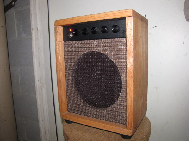
This is an amplifier I designed for busking and just so I could play crazy sounding stuff in the fields around my house here in Sandy Mush. The design is tailored around some key criteria, namely; be able to provide 15 – 20 watts from a nominal 12 volt supply (10-16 volts), have a tube amp sound, reasonable simplicity and great sounding reverb. I am very pleased the final design. This is my primary practice amp now – mainly because I love the way it sounds and also I like seeing the bile drool out of the mouths of my mortified neighbors as I “rock out”.
I am posting links to the original schematic and a version without the reverb – which simplifies the design a bit. I am also posting some pictures of the circuit board, a completed unit and some sound samples.
NOTE* Have updated design and thru-hole layout here: https://circuitsalad.com/2013/03/16/portable-battery-amp-thru-hole-version-schematic-and-layout-link/ this new version uses a new final amp TDA7396 (TDA7360 discontinued)
Click Here To See and Hear:
Schematics:
https://circuitsalad.com/wp-content/uploads/2012/08/portaamp.gif
https://circuitsalad.com/wp-content/uploads/2012/08/portaamp-no-reverb.gif
Pics:
https://circuitsalad.com/wp-content/uploads/2012/08/20-watt-battery-amp.jpg
https://circuitsalad.com/wp-content/uploads/2012/08/battery-amp-circuit-brd.jpg
Samples: recorded with DR1 pocket recorder about 2 feet away
Neck pickup, bass/treble middle setting – no reverb
https://circuitsalad.com/wp-content/uploads/2012/08/dry-blues.mp3
Bridge pickup , bass/treble middle setting – small room reverb 1/3 depth
https://circuitsalad.com/wp-content/uploads/2012/08/not-fade-away_small-room.mp3
Neck pickup, bass/treble middle setting – large room reverb 1/3 depth
https://circuitsalad.com/wp-content/uploads/2012/08/large-room-reverb-noodle.mp3
Features:
Power – I used as the final amplifier a TDA7360 car stereo amplifier in bridged mode. This amp sounds great and can provide 20 + watts through 4 ohms with a 14v supply. Some may shuddered in horror at the thought of this used for a guitar amp, but it really works well and is reasonably efficient, requiring only the circuit board ground plane as heat sinking. I use a small lead/acid gel cel to power this amp but also have used drill batteries and a computer wall wart, etc.
Tube Sound – To achieve a tube like sound I used a classic fender type tone stack, discrete signal chain using jfets (up to the power amp) and negative feedback from the speaker to the final preamp stage. If you look at the circuit, you can see that basically all of the active devices could be replaced with tubes and the TDA7360 with a couple of output tubes and a transformer. The negative feedback from the speaker is a classic technique in tube amps and applied here, has a noticeable effect on the sound.
Simplicity – I set a limit on physical size and number of knobs which forced me to keep it simple.
Reverb – I thought seriously about integrating a spring reverb, but went with a DSP circuit, the FV- 1 chip, instead. This IC provides a number of reverbs and other effects which are selectable via switches(jumpers). It is easy to use and I was able to color the reverb with filtering to my taste. It is essentially an effects unit on a chip. I very pleased with its performance. The reverb has both room size and depth control, and provides all kinds of variation.
Design Notes: There is flexibility in this design – you don’t have to use a switch mode 3.3v power supply for the FV-1 like I did – you could just use a linear regulator. I use a PMOS FET as a NO VOLTAGE DROP protection diode. This could also be omitted. I hate to lose .7 volts with a regular diode though – so I recommend the PMOS approach. The choice of JFET was based on what I had kick’n around – nothing else. I also tried it using LND150’s with similar results. My tone stack is nothing special and many other variations could be used. The volume control at the very front may seem odd. In fact, at very low volume settings, there is treble roll off because of stray capacitance of the POT. The reason I did it was to maximize headroom of the preamp stages and simplicity. This is a design choice that merits a second look. The amount negative feedback from the final to the driver stage is adjustable or can be omitted. A high-end treble control (presence) is realised by bypassing this feedback for very high frequency. This too can be omitted.
For the speaker I used a $22 Jensen 8″ MOD. I highly recommend this speaker – its cheap and sounds perfect.

This is a wonderful ‘buildingblock’ design and you have presented solid information on how to add effects such as reverb and compressors etc. In an easy to understand modular fashion.
In seeking perfection… A pic of a ‘printable’ circuit board (copper artwork?) or reference to suppliers for same if appropriate would be icing on an already good cake!
Thanks for sharing your efforts and work.
Thats great I will work on both. I have done pc boards for my devices shown but mostly for surface mount designs. I will display these and also look at some through hole versions.
Yes I have not posted PCB’s yet. I will try to do that soon.
Excellent project site! I look forward to seeing more from you!
As for the project, what is the purpose of L+ and L-?
I thought I answered this? but the blog is not showing up with my response?…. So I will answer again. The L+ and L- are a poor man’s balanced line out for a mixing board or audio interface. Its a crude attenuator off the main speaker outs but it works just fine to my ear.
I was also wondering if the J309 was chosen particularly, or if a J201 or 2N5457 could work?
No it was not – it is what I had floating around that i could grab. Normally this is an VHF RF amp device but it works well. The others you mentioned will work fine. I also have treid others as well. You may need to tweak your source resistor values slightly to ensure you get maximum output swing – but even if you don’t – I bet it will be close enough.
Cool amp! Question about the bridged amplifier – Does it matter which out is the – and which is the + for the speaker? I’m assuming not, but is it possible to use a line out with this type of set up? I mean with a dummy load resistor, etc. I’m not sure what out to take it from. Thanks!
No it does not matter as you have probably have determined. In my circuit, there is a line out, I just use a resisvtive divider on the outputs. The terminals for the line out are L+ and L-. You can just use one or both for an XLR type differential line out. Its cheap and dirty but works great. The chip I used has been obsoleted, but there is new generation that is almost identical with only a slightly different pinout. I am working on a new schematic and layout based on the new IC (E-TDA7396) for through-hole components. I have just been so busy with work this month I have not got it done yet – but it is comming!
Nice! Thanks for the info on the new chip. I have a line out with a 50W dummy load already built, so I can just take one of the outs? Since it’s a bridged amp, taking only one out would only give me half the intended signal, but I suppose that doesn’t really matter if it’s going into a mixing console or something else. Does anything need to be done to the second output / speak connection, or can that stay connected to the speaker? Thanks!
Many thanks for coming out with the thru hole version of the guitar amp.Thanks also for sizing it for PC Xpress mini bd format .I have just ordered my bds. from PCB Xpress. Regarding the FV-1 chip,OCT distribution only seems to offer complete bds. utilizing the FV-1, at roughly $27.00 ea. Where can I buy just the FV-1 chips? Kudos for your generosity in your offerings. It is much appreciated by me….Joe
small bear and mojo tone has the FV-1. It is $17 from small bear. small bear also has the crystal you need. If you have any problems let me know – maybe I can help. It should be very straight forward to build. Lots of neat things you can do to tailor the tone – Don’t be afraid to change some stuff around!
Ray
On Sat, Mar 23, 2013 at 7:10 PM, Circuit Salad
Yes the sizing is intentional – its a little crammed but the low cost board option makes it worth it.
Where can I get a pcb for this wonderful project?
Thanks
Ed
Hey Ed
There is a link to download the PCB file in expresspcb format. This is web based service I use to crank out boards – its not too expensive either. You need to download the expresspcb layout software( which is free and easy to use) and load the file and then just pick your manufacture option.
Great idea and darn good tones. I am a pro guitarist now for 30 years but a fledgling electronics guy. Wanting to put an amp in this. An old Heathkit Tube Volt Meter V-4A. It already has the phono plug female spot, several potentiometer spots etc. Wondering how I can turn it into a 10-15 Watt amp and then use an external speaker cab.