
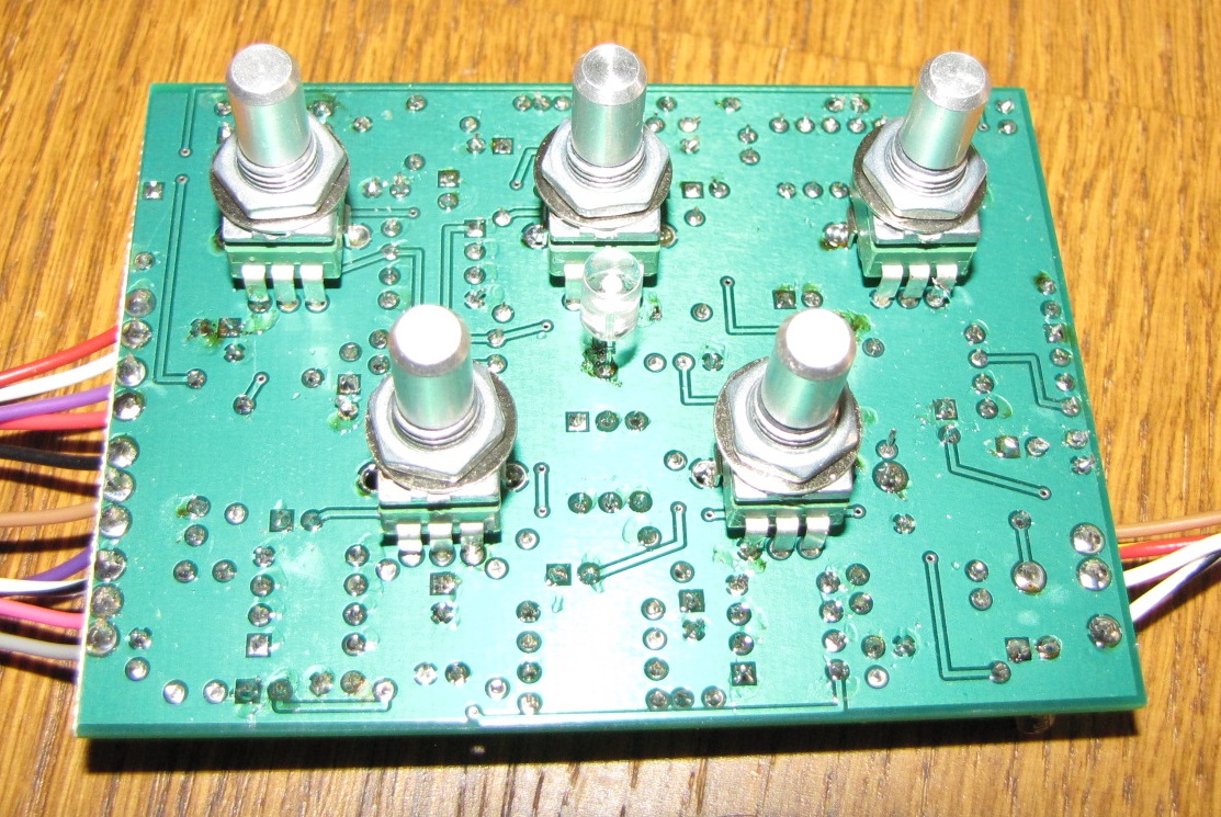
View of the Back Side Where 9mm Alpha POTS Are Mounted
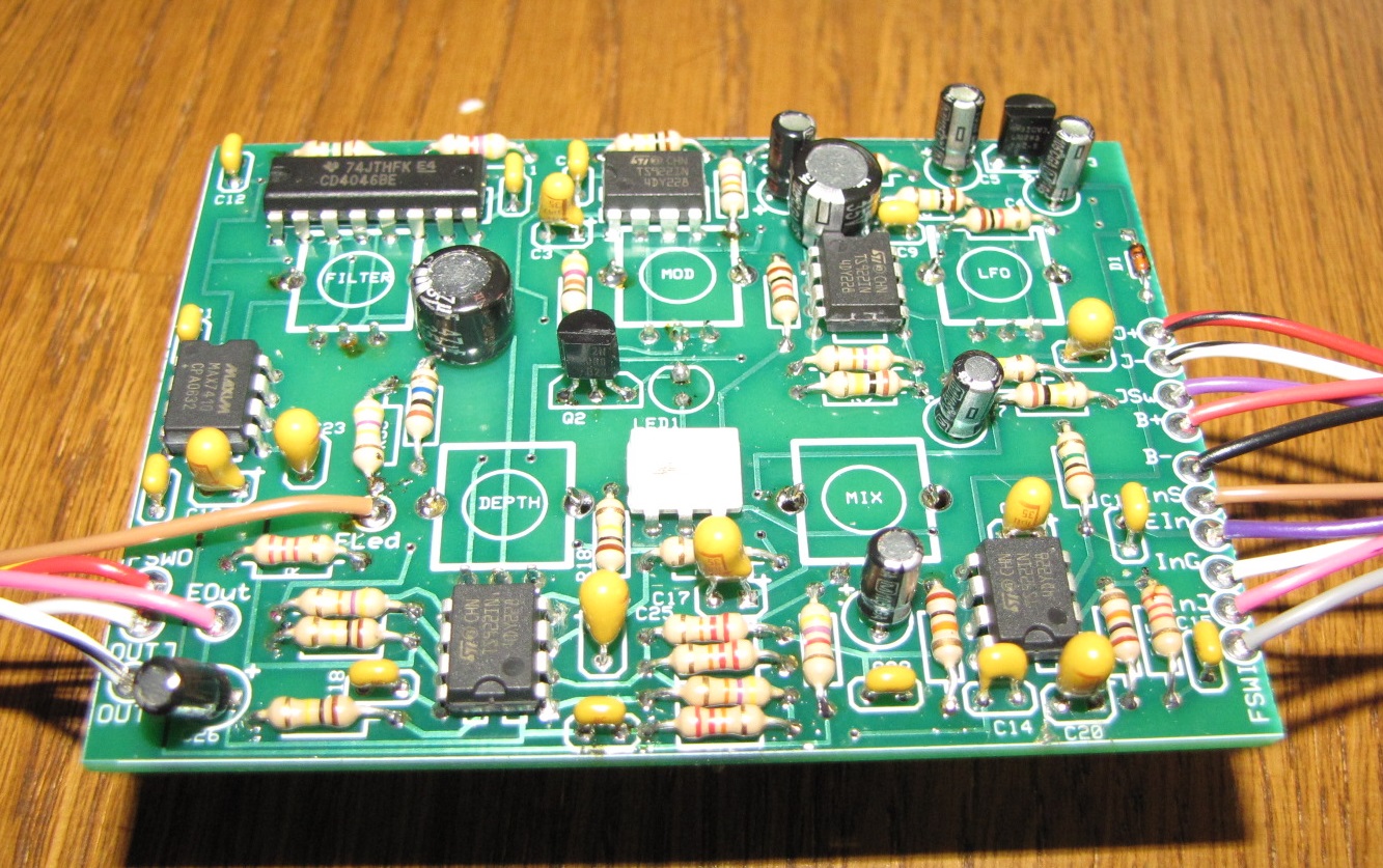
Component Side View
The board layout is tight but very doable. It is designed to fit easily in a 1590BB enclosure and also will fit on the expresspcb’s cheapest prototype service fixed size 2.5 x 3.8 board (3 boards for $59.00 delivered ).
Here is the link to the expresspcb layout: https://www.adrive.com/public/tQPgjW/Ring%20Mod.zip
The Associated Schematic is here:

Couple of notes:
The Blue LED I use has a very high turn on voltage of more than 3V. If you use another type, R13 will definitely need to be increased perhaps to 2.2k or greater. The part I used is from Digikey and the part number is OVLLB8C7.
The design uses 9mm alpha pots mounted on the back. Others can be used just connect wires to the pin connection holes on the board.

I’m very impressed by the range of sound possibilities this circuit offers and would like to try building it. I’ve downloaded the PCB layout, but on checking the costing option in Express PCB, it says that the board does not meet the MiniBoard requirements. Any chance you could check and modify the layout? In fact, any chance that you could sell me a board (even for the MiniBoard deal, Express PCB charge a flat USD59 for postage to the UK)?
Yes I put in a new link which is for the mini-board size -which should work for you. I have one board left which I would give you but I need it so you will have to have some made.
Remember when you use the mini-board service you have a little excess you must cut off to fit in the 1590 BB. Let me know if you have anymore problems.
Hi Ray,
First, I want to say “thank you!” for all the great information and explanations you have shared with the community.
I have a question pertaining to both the Ring Modulator as well as the PWM Compressor. It seems that the TS922 opamp is end of life and very hard to find in a DIP package. I was wondering if you could answer the following:
1) Is there a suitable substitute which is DIP-8 (through hole) and available? Will the TLC272 work in both the Ring Mod and Compressor? Could you sub in a standard 4558 compatible?
2) Did you choose the TS922 for these projects because you have a large supply of them, or is it because the rail-to-rail characteristics are truly needed?
Thank you in advance,
Ben
Ouch!!!!! Yes I just used the op amp because I had a bunch and it has good specs – lots of other possibilities. For me the rail to rail is important in general because it lets me be more lazy about trying to maximize head room…etc. But TLC272 should work fine for example(its voltage noise is a little higher but not a big deal). I am going to look at some other possibilities in DIP and post them. Thanks for the heads up -end life for parts is a constant struggle. https://circuitsaladdotcom.wordpress.com/wp-admin/edit-comments.php?p=583&approved=1#comments-form
Ray, that is superb! Thank you. I figured that you had a stash of them as they are in many of your builds posted here.
Also curious if you knew the specs on the TS922 that you use (part suffix would help). It seems there are a few variants with different input offset voltages in 500uV, 900uV, and 3mV…is it imperative that the offset voltage matches the version you have for proper operation?
TS922(A) 900uA – not that important with regard to ofset
Ray- in love with this circuit- i would love to get the PCB, but the fileswap link is down now.. any way that i could get that?
yes – I will get the link back up- don’t know what happened?
New link is up – so go try again. Also look at my PIC DDS. I say this because you could use this circuit for the VLF oscillator and the modulator drive. It would reduce parts count quite a bit! Having said this nothing wrong with the original circuit.
excellent, thanks again!
yes I built this modulator for a couple players who really like it. It can generate some really synth like sounds but with the nice dynamics of the guitar. If you build it – let me know if you have any issues.. I built three by my own layout and schematic and all worked well – you don’t have to use the TS922 op amp
Where is the part list for this? Just on the schematic? It sounds awesome! I’m going to try and put it together soon. Thanks!
Yes all the parts are on the schematic- many of them are not critical and I just used what I had …you can use other op amps and whatever type passives(resistors and caps) you want. IC3(the regulator) doesn’t matter – any 5v reg will do. You must use a CD4046 not a 74HC4066. This is because the 74 series device has abrupt VCO behavior at the high end. A TL072 will for example for the op amp. If you have any questions let me know
Cool. Any recommendation for online stores to get some of these parts? I usually go on Tayda electronics but they don’t have the optocoupler or the filter.
Yes Tayda is good but they only have what they have. Ebay can have just about anything…also digikey and mouser. Normally i get this stuff from digikey.
BTW the link to the PCB file is still broken 😦
The new link is up in place of the old one at this post: https://circuitsalad.com/2013/06/23/ring-modulator-pcb-info-and-misc-notes/
I will update the link with one that works in the next day or so
I have a few more questions:
would it make sense to try different wave forms for the two oscillators, e.g., square/triangle/sine?
is it possible to change the filter resonance?
is it possible to turn the filter on without modulation (0 frequency)?
Thanks again!
The waveforms don’t make that much difference.I like the triangle wave. I don’t think you can change the resonance.
yes the depth control makes the modulation depth vary from 0 up to 50%.
This looks nice and I’d like to build one …. however, the link to the pcb is down again….
thanks, sounds amazing!
//Micke
will get you a new stable link shortly
Hi Ray!
Thank you so much for this amazing schematic! I put it down on my breadboard and it works very fine. Just a little noticeable problem, there is a little modulation leakage at the high end, as you mentioned on a previous post. Did you fixed it or is it still on the final version?
Thanks,
Antho
A clean layout with short direct signal path connections and using a well defined ground plane and circuit board fixed it.. could also be done on perf neatly
Thanks for your reply! I’ll try it
The download PCB layout link seems to doesn’t work anymore
Hi Ray,
Do you still have the layout? Could you share it please? 🙂
Thanks
I know this is a very old thread, but I was hoping you still check it. This is a great sounding project, and I love me a good ring mod.
Someone gifted me a completed pcb but I don’t have any of the documentation. I want to make sure that I understand all of the hookups. I believe I can identify the dry and wet signal ins and outs but I’m not 100% on what everything else is.
I’ll look it over
and get back with you
Hello…
You will have the PCB to print, the link you have published already expired.
I will post this for you in a day or so …a useable link
Thanks, I will wait
Hi Ray,
The link to the pcb file appears to be down again. Can you re-share/upload? I’m excited to try building this!
I will get a link set up will take a day or two
Thanks so much. Hate to ask, but do you mind throwing up a post when you do get the link working? Feel like I’m stalking the post this week, haha!
Link has been updated on original post…here it is also: https://www.adrive.com/public/tQPgjW/Ring%20Mod.zip