I fry a lot of electronics – so I like to include reverse polarity protection when I can. But there is a problem with using a traditional silicon diode, namely dropping .7 volts across the diode(more with high current). Consider that in an earlier post I described a 20 watt, amp I designed. If this amplifier is drawing 1 amp, a standard silicon diode wastes .7 Watts or more!
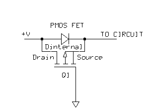
A better choice is to use a PMOS FET as shown in the picture below:
The way it works is that the Gate is grounded and only when the SOURCE is at a higher potential than the GATE will the PMOS conduct across from Drain to Source. This only occurs when the supply voltage conducts across the internal substrate diode(Dinternal), energizing the SOURCE and allowing conduction. When the PMOS is turned on, the drop across the mosfet is only millivolts (depending on the mosfet specs), much less than a traditional diode.


This is the best solution for low voltage equipments!