
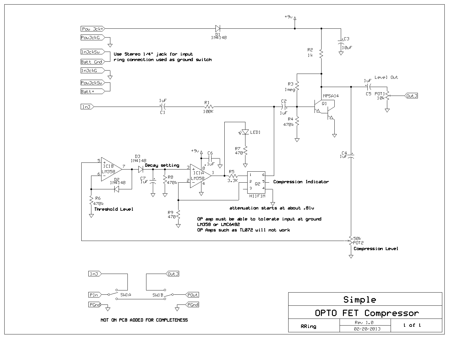
I have been playing with all sorts compressor ideas and the circuit below is about the simplest thing I have come up with that works well. It uses just a handful of parts and needs no critical adjustments. It has fast attack and slow decay – which I find the most useful for guitar.
here is the schematic:
https://circuitsalad.com/wp-content/uploads/2013/03/simple-opto-comp1.gif
Additional notes here:
https://circuitsalad.com/2013/03/30/some-possible-value-mods-for-the-simple-opto-compressor/
link to ExpressPCB layout:
http://www.fileswap.com/dl/PFYBP3Gwp4/
It utilizes a number of features from my other designs and I have also integrated some suggestions from other designers (like using a darlington for the amp stage).
This design has the folowing features:
a H11F1m OPTO FET variable resistor to control gain.
a darlington transistor as a shunt/shunt feedback amplifier. The biasing and feedback (from the collector to base) is critical to the design. The reason is that it keeps the voltage across the OPTO FET very low so as to keep it’s behavior linear. With out this feedback – there can be distortion.
LM358 beef stew op amp as a compensated diode peak detector and as a current mode amplifier the drive the H11F1m OPTO FET variable resistor.
The LED indicator is tied to the compression feedback loop and indicates compression level with variable brightness.
Demo comming soon.

